


2-5
Cisco ME 4924-10GE Ethernet Switch Hardware Installation Guide
OL-10071-01
Chapter 2 Switch Installation
Preparing for Installation
• None (flow control)
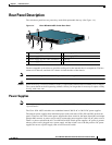
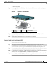
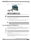
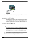
Step 2 Use the supplied RJ-45-to-DB-9 adapter cable to insert the RJ-45 connector into the console port, as
shown in Figure 2-1.
Figure 2-1 Connecting to the Console Port
Step 3
Attach the DB-9 female DTE adapter of the RJ-45-to-DB-9 adapter cable to a PC, or attach an
appropriate adapter to the terminal.
Step 4 Start the terminal-emulation program if you are using a PC or terminal.
Powering On the Switch and Running POST
To power on the switch, follow these steps:
Step 1 Make sure that you have started the terminal emulation software program (such as ProComm,
HyperTerminal, tip, or minicom) from your management station. See the “Connecting a PC or Terminal
to the Console Port” section on page 2-4 for information on connecting to the switch console port.
Step 2 If you are using an AC power supply, connect one end of the AC power cord to the AC power connector
on the switch, and then connect the other end of the power cord to an AC power outlet.
Step 3 If you are using a DC power supply, see the “Connecting DC Power to the Cisco ME 4924-10GE Switch”
section on page 3-3 for instructions on how to connect the DC power supply.
Step 4 Secure the power cord with the power cord retainer. For more information, see the “Connecting AC
Power to the Cisco ME 4924-10GE Switch” section on page 3-2.
1 Cisco ME
4924-10GE
2 PC 3 Console cable
154861
13
14
15
16
17
1
8
19
20
21
22
23
24
1
2
3
C
is
c
o
M
E
4
9
2
4
-
1
0
G
E