


1-4
Cisco ME 4924-10GE Ethernet Switch Hardware Installation Guide
OL-10071-01
Chapter 1 Product Overview
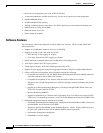
Front Panel Description
Management Port
The management port is used (in ROMMON mode only) to recover a switch software image that has
been corrupted or destroyed due to a network catastrophe. This port is not active while the switch is
operating normally.
You should designate one of the normalports on your switch as a management port, used for
configuration and monitoring traffic. D o not connect the management port to this network, it is only
intended to be used from a direct console connection.
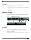
SFP Module Ports
The switch uses Gigabit Ethernet SFP modules to establish fiber-optic connections. These transceiver
modules are field-replaceable, providing the uplink interfaces when inserted in an SFP module port.
You can use the SFP modules for Gigabit uplink connections to other switches. You use fiber-optic
cables with LC connectors to connect to a fiber-optic SFP module. You use Category 5 cable with RJ-45
connectors to connect to a copper SFP module.
For more information about these SFP modules, refer to your SFP module documentation.
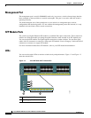
LEDs
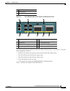
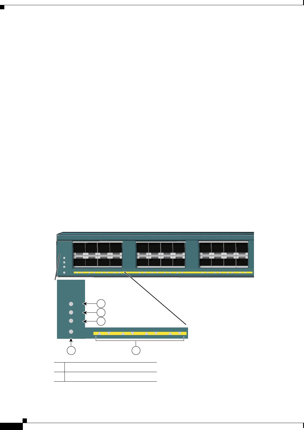
You can use the switch LEDs to monitor switch activity and performance. Figure 1-2 and Figure 1-3
show the switch LEDs.
Figure 1-2 Cisco ME 4924-10GE Switch LEDs
1 Power Supply 1 LED
2 Power Supply 2 LED
1 2 3 4 5 6 7 8
1 2 3 4 5 6 7 8
9 10 11 12 13 14 15 16 17 18 19 20 21 22 23 24
STATUS
PS1
PS2
FAN
STATUS
PS1
PS2
FAN
154870
1
2
3
4 5