


2-12
Cisco ME 4924-10GE Ethernet Switch Hardware Installation Guide
OL-10071-01
Chapter 2 Switch Installation
Connecting to an SFP Module
Connecting to 1000BASE-T SFP Modules
Follow these steps to connect a Category 5 cable to a 1000BASE-T SFP module:
Caution To prevent ESD damage, follow your normal board and component handling procedures. Keep
components in antistatic bags or on antistatis mats when not in use, wear a grounding strap while
handling components, and follow other ESD prevention guidelines appropriate to your environment.
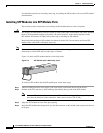
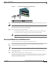
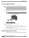
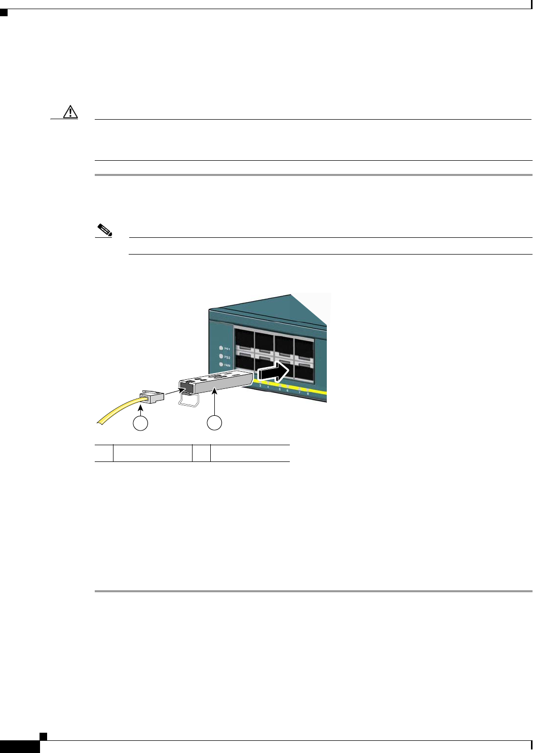
Step 1 When connecting to servers, workstations, and routers, insert a four-twisted-pair, straight-through cable
in the RJ-45 connector. When connecting to switches or repeaters, insert a four-twisted-pair crossover
cable. (See Figure 2-8.)
Note When connecting to a 1000BASE-T device, be sure to use a four-twisted-pair, Category 5 cable.
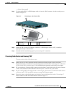
Figure 2-8 Connecting to a 1000BASE-T SFP Module Port
Step 2
Insert the other cable end in an RJ-45 connector on a target device.
Step 3 Observe the port status LED.
The LED turns green when the switch and the target device have an established link.
If the LED is off, the target device might not be turned on, there might be a cable problem, or there might
be problem with the adapter installed in the target device. See Chapter 4, “Troubleshooting” for
solutions to cabling problems.
Step 4 If necessary, reconfigure and restart the switch or target device.
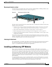
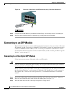
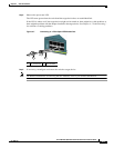
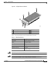
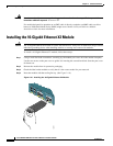
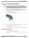
X2 Module Handling Guidelines and Installation
An X2 module (see Figure 2-9) is a hot-swappable input/output device that plugs into the 10-Gigabit
Ethernet port of the Cisco ME 4924-10GE switch and links the switch with a fiber-optic network.
1 RJ-45 connector 2 SFP module
P
S
1
P
S
2
F
A
N
154921
2
1