


1-8
Cisco ME 4924-10GE Ethernet Switch Hardware Installation Guide
OL-10071-01
Chapter 1 Product Overview
Management Options
The switch will start with only one power supply plugged in, but redundant failover and load sharing
will not be available in this configuration. We recommend that you always connect both power supplies
to separate AC or DC circuits for optimal power reliability.
For safety reasons, the AC power supply needs to be switched off and unplugged before it is removed
from a chassis or inserted into a chassis. DC supplies should have power shut off from the source before
they are removed.
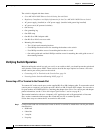
If only one power supply will be used, you must use the blank faceplate supplied to cover the empty
power bay.
Environmental Monitoring of the Power Supplies
Using the environmental monitoring and reporting functions, you can maintain normal system operation
by resolving adverse environmental conditions prior to loss of operation.
Each power supply monitors its own temperature and output voltages. If conditions reach critical
thresholds, the power supply might shut down to avoid damage from excessive heat or electrical current.
The Cisco ME 4924-10GE switch senses the operating condition of the power supply and reports status
through software.
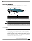
Power Management for the Cisco ME 4924-10GE Switch
You can select AC or DC power supplies for your switch. The Cisco ME 4924-10GE switch supports
the following power supplies:
• 300 WAC
• 300 W DC
A redundant power supply can be identified and diagnosed by a running system regardless of its input
status. AC and DC supplies are interchangeable.
Power Management Modes
The Cisco ME 4924-10GE switch supports the redundant power management mode. In this mode, if
both power supplies are operating normally, each provides from 20/80 to 45/55 percent of the total
system power requirements at all times. If one power supply fails, the other unit increases power to 100
percent of the total power requirement.
Management Options
The switch offers several management options:
• Cisco IOS command-line interface (CLI)
You can fully configure and monitor the switch from the CLI. You can access the CLI either by
connecting your management station directly to the switch console port or by using Telnet from a
remote management station. To create a partial configuration that will allow remote setup using the
CLI, see Appendix C, “Initial Configuration for the Switch,” and refer to the Catalyst 4500
Command Reference on Cisco.com for more information about using the CLI for a more complete
configuration.