


78-11719-02 July 2001 Using Cisco Transport Controller 3
Cisco ONS 15327 User Documentation 3-15
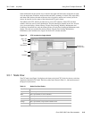
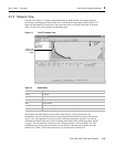
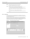
3.5.2 Network View
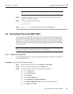
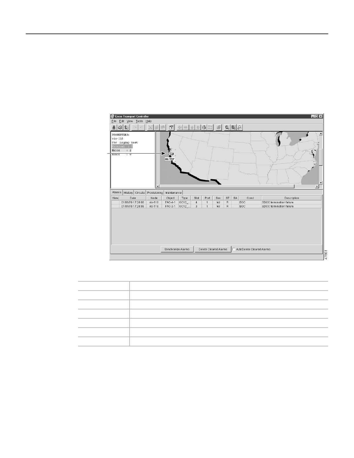
Network view (Figure 3-7) displays information about the ONS network. You perform network
provisioning and management tasks in this view. A United States map displays and the ONS 15327
nodes are represented by colored icons. The color of the node icon indicates the status of the node.
Table 3-3 shows the colors and their corresponding status.
Figure 3-7 The CTC network view
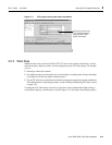
The network view tabs display network alarms, alarm history, circuits, provisioning, and
maintenance. You can click spans (the lines connecting the nodes) and node icons on the network
map to view circuit properties, provision circuits, and perform protection switches. You can also
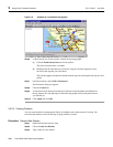
customize the network map view (see the “Inserting an Alternative Network Topology Map” section
on page 3-16) and create new domains (see the “Creating Domains” section on page 3-18). This
customized map view becomes the default view for that user, when the user navigates out of the
network view. Table 3-4 shows the actions that you can perform in network view.
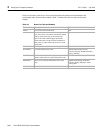
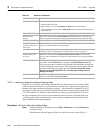
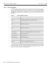
Table 3-3 Node Status
Color Alarm Status
Green No alarms
Yellow Minor alarms
Orange Major alarms
Red Critical alarms
Grey with node name Node is initializing
Grey with IP address Node is initializing, or a problem exists with IP routing from node to PC
Node color
indicates its
status