


78-11719-02 July 2001 Using Cisco Transport Controller 3
Cisco ONS 15327 User Documentation 3-41
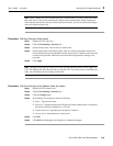
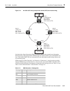
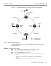
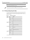
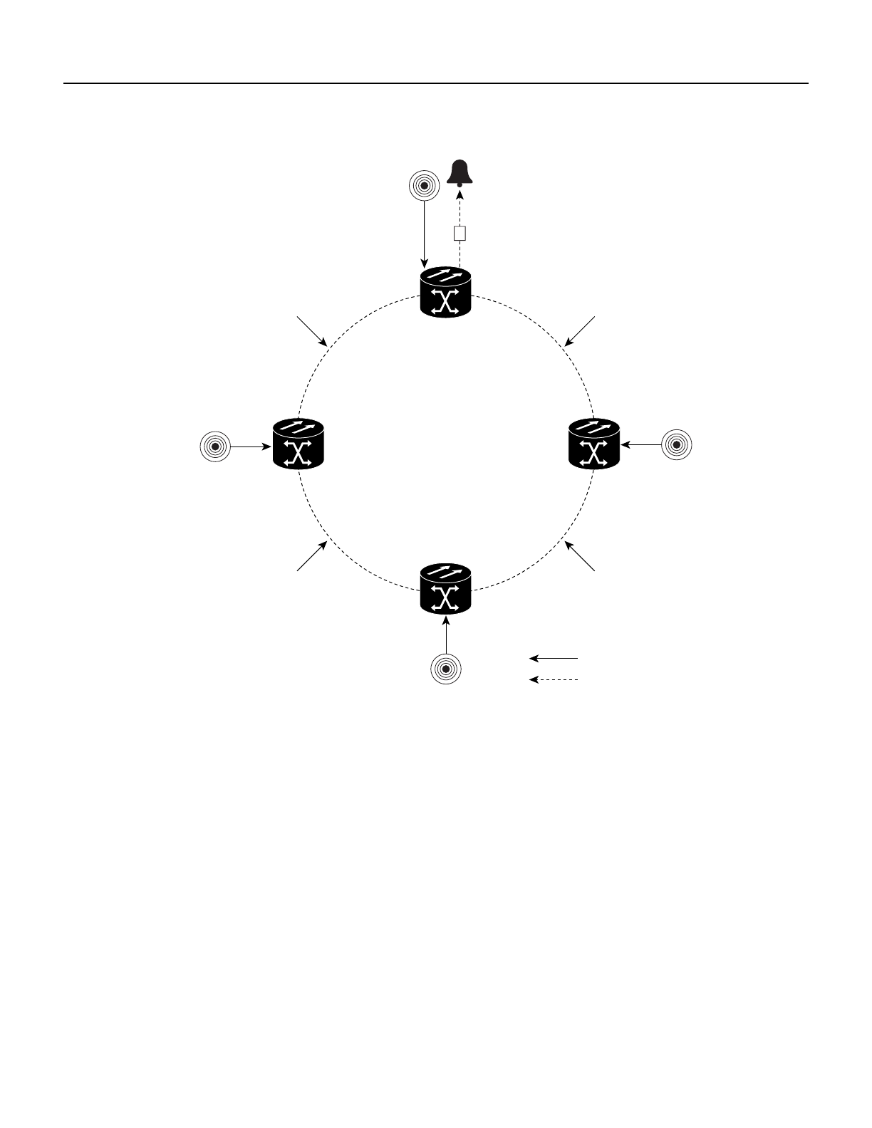
Figure 3-23 Example of external alarms and controls in a virtual wire configuration
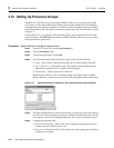
3.12.2 External Input Alarms
Use external alarms for sensors such as open doors, temperature sensors, flood sensors, and other
environmental conditions.
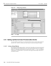
Procedure: Provision External Alarms
Step 1 Wire the external-device relays to the Alarm RJ-45 connector on the MIC.
Step 2 Log into CTC and display the working XTC card in card view.
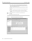
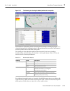
Step 3 Click the External Alarms subtab (Figure 3-24).
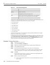
Step 4 Complete the following fields for each external device wired to the RJ-45 connector on
the MIC card:
• Enabled—Click the box to activate the fields for the corresponding alarm input
number.
• Alarm Type—Select an alarm type from the list provided.
ONS 15327
Node 1
Virtual Wire #1 is
external control
trigger
Virtual Wire #1
Smoke
detector
Bell
Smoke
detector
ONS 15327
Node 2
ONS 15327
Node 3
ONS 15327
Node 4
Virtual Wire #1
Virtual Wire #1 Virtual Wire #1
= External alarm
= External control
Smoke
detector
Smoke
detector
55002