


78-11719-02 July 2001 Using Cisco Transport Controller 3
Cisco ONS 15327 User Documentation 3-43
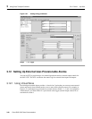
3.12.3 External Output Controls
Use external controls, or office alarms, to drive visual or audible devices such as bells and lights. The
alarm-triggering conditions for the external controls can be the user-defined external input alarms
(virtual wire), local severity-based alarms (e.g. trigger when any Major alarm happens), or remote
severity-based alarms.
Procedure: Provision External Controls
Step 1 Wire the external control relays to the ALARM RJ-45 connector on the MIC.
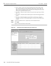
Step 2 In CTC, log into the node and display the XTC card view.
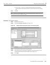
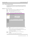
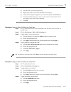
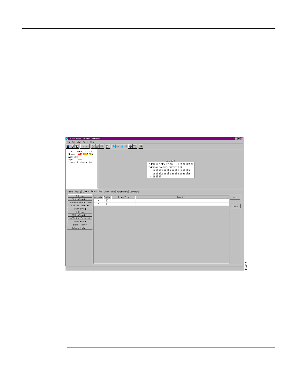
Step 3 Click the External Controls subtab as shown in Figure 3-25.
Figure 3-25 The External Controls subtab showing the XTC-28-3 card
Step 4
Complete the following fields for each external control wired to the Alarm connector on
the MIC:
• Enabled—Click the box to activate the fields for alarm input number 1 or 2.
• Trigger Type—Select a trigger type: a local Minor, Major, or Critical alarm; a remote
Minor, Major, or Critical alarm; or a virtual wire activation.
• Description—Enter a description.
Step 5 To provision additional controls, complete Step 4 for each additional device.
Step 6 Click Apply.
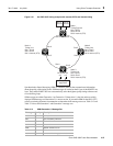
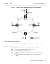
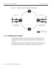
Figure 3-26 shows a functional diagram of alarm input and output.