


3 Using Cisco Transport Controller 78-11719-02 July 2001
Cisco ONS 15327 User Documentation3-16
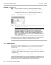
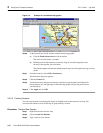
3.5.2.1 Inserting an Alternative Network Topology Map
With CTC you can install a custom map for the network view. The map needs to be in either a JPEG
or GIF file format and stored on an accessible local or network drive. Approximate longitudes and
latitudes for the edge coordinates of the map are required — this information is included on U.S.G.S.
topographical maps, and you can obtain the longitude and latitude for cities and Zip Codes from the
U.S. Census Bureau U.S. Gazetteer website (http://www.census.gov/cgi-bin/gazetteer). CTC uses
the edge coordinates of the custom map to determine the relative positions of the ONS node icons
on the map graphic. Edge coordinates only need to be precise enough to place ONS node icons in
approximate positions on the map graphic.
Procedure: Set Up an Alternative Network Map
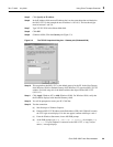
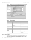
Step 1 From the menu bar in network view, choose Edit > Preferences or click the Preferences
tool in the toolbar.
The Preference dialog box appears (Figure 3-8) with the four tabs listed in Table 3-5.
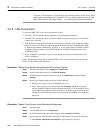
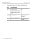
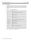
Table 3-4 Network View Actions
Action Procedure
Open a node Any of the following:
• Double-click the node icon
• Right-click the icon, choose Drill Down to Node from the shortcut menu
• From the CTC Go To menu, choose Other Node, then choose the node from the Select
Node dialog box
Move a node icon Pressing the Control <Ctrl> and left mouse buttons, drag the node icon to a new location.
Reset node icon
position
Right-click a node and choose Reset Position from the shortcut menu. The node icon
moves to the position defined by the longitude and latitude fields on the General subtab.
Display span properties Click a network span. Properties display in the upper left corner of the window.
Perform a UPSR
protection switch for an
entire span
Right-click a network span and click Circuits. See the “Switch UPSR Traffic” section on
page 4-7 for UPSR protection switch procedures.
Provision a circuit Right-click a node and choose Provision Circuit To from the shortcut menu. For circuit
procedures, see the “Creating and Provisioning Circuits” section on page 4-18.
Update circuits with
new node
Right-click a node and choose Update Circuits With New Node from the shortcut
menu. Use this command when you add a new node and want to pass circuits through the
new node.
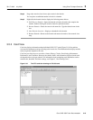
Customize map view To zoom in on the map graphic, click the Zoom In tool in the toolbar. To zoom out on the
map graphic, click the Zoom Out tool. Clicking on the
Zoom Selected Area tool
turns your cursor into a crosshair: hold down the left mouse button and drag the
crosshair diagonally across the area. The selected area will be zoomed. You can
also right-click on the map graphic and select Zoom In, Zoom Out, Zoom
Selected Area, Set Background Color, Set Background Image, Remove
Background Image.
Create New Domain Right-click the map graphic with your mouse pointed anywhere on the map (but not at a
node icon) and choose Create New Domain.