


Overview 1-15
LEDs
LEDs
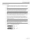
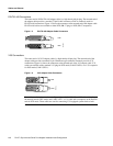
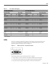
The PA-4T+ contains the enabled LED, standard on all port adapters, and one status LED for each
port. After system initialization, the enabled LED goes on to indicate that the PA-4T+ has been
enabled for operation. (The LEDs are shown in Figure 1-9.)
Figure 1-9 LEDs on the PA-4T+—Horizontal Orientation
The following conditions must be met before the PA-4T+ is enabled:
• The port adapter is correctly connected to the backplane midplane and receiving power.
• A valid system software image for the port adapter has been downloaded successfully.
• The system software recognizes the port adapter or VIP2 with an installed PA-4T+.
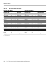
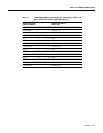
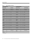
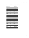
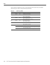
Table 1-7 X.21 Adapter Cable Signals
DTE Cable (CAB-X21MT=) DCE Cable (CAB-X21FC=)
Router End, HD
1
60-Position Plug
1 HD = high density.
Network End,
DB-15 Plug
Router End, HD
60-Position Plug
Network End,
DB-15 Receptacle
Signal Pin Pin Signal Signal Pin Pin Signal
Shield ground 46 1 Shield ground Shield ground 46 1 Shield ground
TxD/RxD+ 11 —> 2 Transmit+ RxD/TxD+ 11 —> 2 Transmit+
TxD/RxD– 12 —> 9 Transmit– RxD/TxD– 12 —> 9 Transmit–
RTS/CTS+ 9 —> 3 Control+ CTS/RTS+ 9 —> 3 Control+
RTS/CTS – 10 —> 10 Control– CTS/RTS – 10 —> 10 Control–
RxD/TxD+ 28 <— 4 Receive+ TxD/RxD+ 28 <— 4 Receive+
RxD/TxD– 27 <— 11 Receive– TxD/RxD– 27 <— 11 Receive–
CTS/RTS+ 1 <— 5 Indication+ RTS/CTS+ 1 <— 5 Indication+
CTS/RTS – 2 <— 12 Indication– RTS/CTS– 2 <— 12 Indication–
RxC/TxCE+ 26 <— 6 Timing+ TxC/RxC+ 26 <— 6 Timing+
RxC/TxCE– 25 <— 13 Timing– TxC/RxC – 25 <— 13 Timing–
Circuit ground 15 8 Circuit ground Circuit ground 15 8 Circuit ground
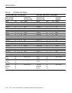
Ground
Mode_2
48
47
Shorting group Ground
Mode_2
48
47
Shorting
group
Ground
Mode_DCE
51
52
Shorting group Ground
Mode_DCE
51
52
EN
H4491
TD
TC
RD
RC
LB
CD