


Checking the Configuration
PA-4T+ Synchronous Serial Port Adapter Installation and Configuration8-18
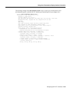
VIP2 show interfaces Command
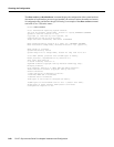
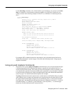
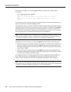
Following areexamples ofhowthe showinterfaces [type slot/port-adapter/port] commanddisplays
status information (including the physical slot and port address) for the interfaces you specify. The
four PA-4T+ interfaces (0–3) are in interface processor slot 3, in port adapter slot 1.
Router# show interfaces serial 3/1/0
Serial3/1/0 is up, line protocol is up
Hardware is cyBus Serial
Internet address is 10.10.10.1
MTU 1500 bytes, BW 1544 Kbit, DLY 20000 usec, rely 255/255, load 1/255
Encapsulation PPP, loopback not set, keepalive set (10 sec)
[display text omitted]
Router# show interfaces serial 3/1/1
Serial3/1/1 is up, line protocol is up
Hardware is cyBus Serial
Internet address is 10.10.10.2
MTU 1500 bytes, BW 1544 Kbit, DLY 20000 usec, rely 255/255, load 1/255
Encapsulation PPP, loopback not set, keepalive set (10 sec)
[display text omitted]
Router# show interfaces serial 3/1/2
Serial3/1/2 is up, line protocol is up
Hardware is cyBus Serial
Internet address is 10.10.10.3
MTU 1500 bytes, BW 1544 Kbit, DLY 20000 usec, rely 255/255, load 1/255
Encapsulation PPP, loopback not set, keepalive set (10 sec)
[display text omitted]
Router# show interfaces serial 3/1/3
Serial3/1/3 is up, line protocol is up
Hardware is cyBus Serial
Internet address is 10.10.10.3
MTU 1500 bytes, BW 1544 Kbit, DLY 20000 usec, rely 255/255, load 1/255
Encapsulation PPP, loopback not set, keepalive set (10 sec)
[display text omitted]