


Identifying Port Adapter Slot and PA-4T+ Interface Port Numbers
PA-4T+ Synchronous Serial Port Adapter Installation and Configuration8-4
VIP2 Ports
In the router, physical port addresses specify the actual physical location of each interface port on
the routerinterface processorend. (See Figure 8-3.)This address iscomposed of athree-part number
in the format interface processor slot number/port adapter number/interface port number.
Note Although the processor slots in the 7-slot Cisco 7000 and Cisco 7507 and 13-slot Cisco 7513
are vertically oriented and those in the 5-slot Cisco 7010 and Cisco 7505 are horizontally oriented,
all models use the same method for slot and port numbering.
• The first number identifies the interface processor slot in which the VIP2 is installed.
• The second number identifies the port adapter slot on the VIP2, and is either 0 or 1.
• The third number identifies the interface ports on each PA-4T+, which are always numbered in
sequence as interface 0 through 3.
Interface ports on a PA-4T+ that is installed in a VIP2 maintain the same address regardless of
whether other interface processors are installed or removed. However, when you move a VIP2 to a
different slot, the first number in the address changes to reflect the new slot number.
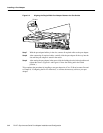
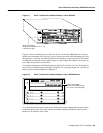
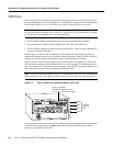
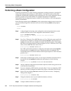
Figure 8-3 shows some of the port adapter slot and interface ports of a sample Cisco 7505 router.
The interface port addresses for the installed PA-4T+ are 3/1/0 through 3/1/3 (interface processor
slot 3, port adapter slot 1, and interface ports 0 through 3). If the PA-4T+ was in port adapter slot 0,
these same interface ports would be numbered 3/0/0 through 3/0/3.
Note If you remove the VIP2 (shown in Figure 8-3) from interface processor slot 3 and install it in
interface processor slot 2, the addresses of those same PA-4T+ ports become 2/1/0 through 2/1/3.
Figure 8-3 PA-4T+ Interface Port Address Example—Cisco 7505
You can identify interface ports by physically checking the slot/port adapter/interface port location
on the back of the router or by using show commands to display information about a specific
interface or all interfaces in the router.
H9707
Slot 0
Slot 1
Slot 2
Slot 3
Interface
processor
slots
EJECT
SLOT 0
SLOT 1
NORMAL
CPU HALT
RESET
CONSOLE
ROUTE SWITCH PROCESSOR
FAST SERIAL, ENHANCED
PA-4T+ port adapter
(interface port addresses 3/1/0,
3/1/1, 3/1/2, 3/1/3 from left to right)
0
1
2
3
LINK
0
1
2
3
ETHERNET 10BT
CD
LB
RC
RD
TC
TD
CD
LB
RC
RD
TC
TD
CD
LB
RC
RD
TC
TD
CD
LB
RC
RD
TC
TD
TD