


Installing a Port Adapter
PA-4T+ Synchronous Serial Port Adapter Installation and Configuration4-4
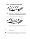
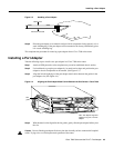
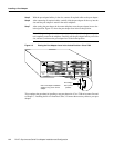
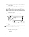
Step 5 With the port adapter halfway in the slot, connect all required cables to the port adapter.
Step 6 After connecting all required cables, carefully slide the port adapter all the way into the
slot until the port adapter is seated in the router midplane.
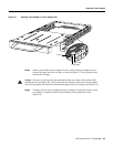
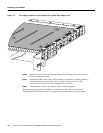
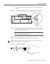
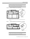
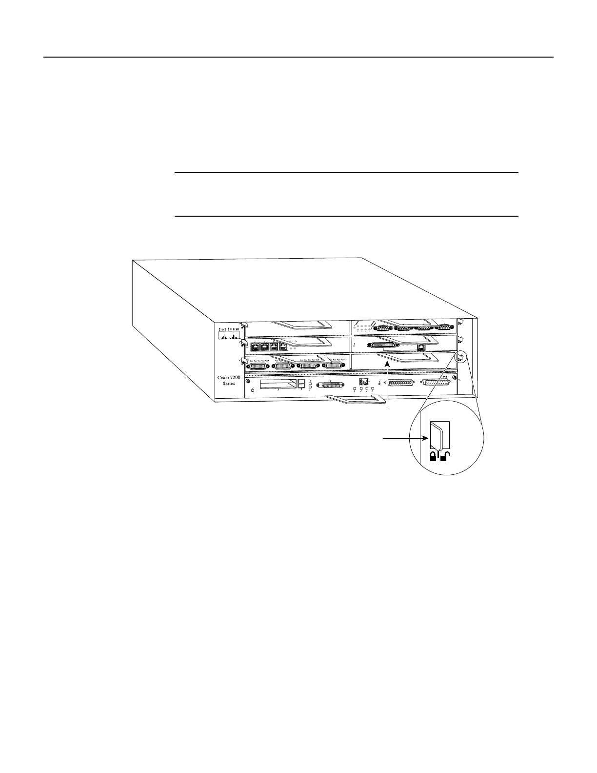
Step 7 After seating the port adapter in the router midplane, move the port adapter lever to the
locked position. Figure 4-5 shows the port adapter lever in the locked position.
Note If the port adapter lever does not move to the locked position, the port adapter is
not completely seated in the midplane. Carefully pull the port adapter halfway out of the
slot, reinsert it, and move the port adapter lever to the locked position.
Figure 4-5 Placing the Port Adapter Lever in the Locked Position—Cisco 7206
This completes the procedure for installing a new port adapter in a Cisco 7200 series router. Proceed
to Chapter 7, “Installing the PA-4T+ Interface Cables,” to connect the necessary cables to your port
adapter.
ETHERNET 10BT
ENABLED
0
2
1
3
LINK
0
1
2
3
FAST SERIAL
EN
TD
TC
RD
RC
LB
CD
TD
TC
RD
RC
LB
CD
TD
TC
RD
RC
LB
CD
TD
TC
RD
RC
LB
CD
ENABLED
MII
LINK
RJ45
FAST ETHERNET
0
TOKEN RING
0
1
2
3
0
2
4
1
3
5
6
H6747
MII
EN
RJ45
EN
RJ45
LINK
1O PWR
OK
RJ-45
CPU RESET
FAST ETHERNET INPUT/OUTPUT CONTROLLER
ENABLED
PCMCIA
EJECT
SLOT 0
SLOT 1
FE MII
Port adapter
handle
Port adapter
lever (locked
position)
Note: This adapter installation
applies to any port or service
adapter.