


Cisco 7200 Series and the PA-4T+ Port Adapter 4-3
Installing a Port Adapter
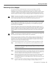
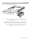
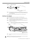
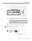
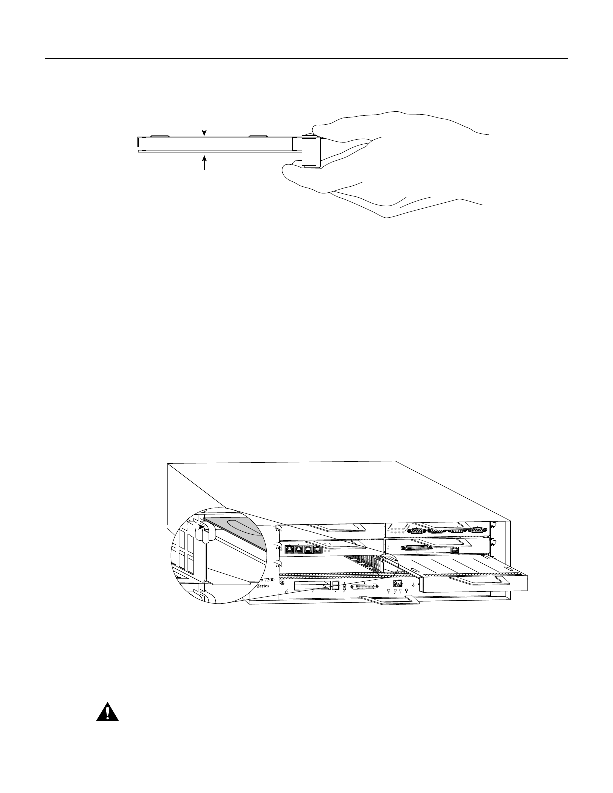
Figure 4-3 Handling a Port Adapter
Step 6
Place the port adapter on an antistatic surface with its components facing upward, or in a
static shielding bag. If the port adapter will be returned to the factory, immediately place
it in a static shielding bag.
This completes the procedure for removing a port adapter from a Cisco 7200 series router.
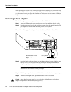
Installing a Port Adapter
Take the following steps to install a new port adapter in a Cisco 7200 series router:
Step 1 Attach an ESD-preventive wrist strap between you and an unfinished chassis surface.
Step 2 Use both hands to grasp the port adapter by its metal carrier edges and position the port
adapter so that its components are downward. (See Figure 4-3.)
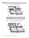
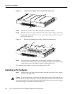
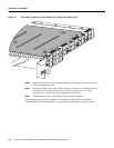
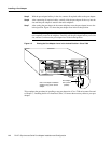
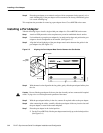
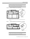
Step 3 Align the left and right edge of the port adapter metal carrier between the guides in the
port adapter slot. (See Figure 4-4.)
Figure 4-4 Aligning the Port Adapter Metal Carrier Between the Slot Guides—Cisco 7206
Step 4
With the metalcarrier aligned in the slot guides, gentlyslide the port adapter halfway into
the slot.
Caution Do not slide the port adapter all the way into the slot until you have connected all required
cables. Trying to do so will disrupt normal operation of the router.
H6420
Metal carrier
Printed circuit board
H6597
MII
EN
RJ45
EN
RJ45
LINK
1O PWR
OK
RJ-45
CPU RESET
FAST ETHERNET INPUT/OUTPUT CONTROLLER
ENABLED
PCMCIA
EJECT
SLOT 0
SLOT 1
FE MII
2
4
6
1
3
5
ETHERNET 10BT
ENABLED
0
2
1
3
LINK
0
1
2
3
ENABLED
MII
LINK
RJ45
FAST ETHERNET
0
TOKEN RING
0
1
2
3
Slot
guide
Note: This adapter alignment
applies to any port or service
adapter.