


Configuring the PA-4T+ Interfaces 8-3
Cisco 7200 Series and Cisco uBR7200 Series Ports
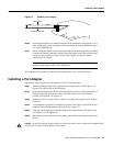
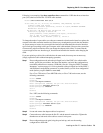
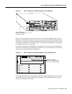
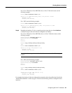
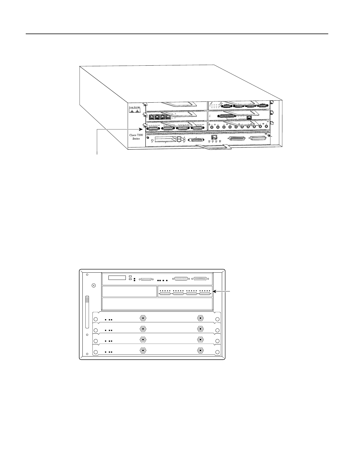
Figure 8-1 PA-4T+ Interface Port Address Example—Cisco uBR7246
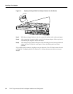
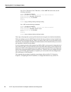
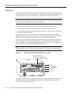
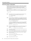
Figure 8-2 shows the interface ports of a PA-4T+ in slot 2 of the Cisco uBR7200 series. The port
adapter slot are numbered slot 1 and slot 2 (slot 0 is always reserved for the Fast Ethernet porton the
I/O controller—if present). The individual interface port numbers always begin with 0. The number
of additional ports depends on the number of ports on a port adapter. Port adapters can occupy any
port adapter slot; there are no restrictions.
For example, the addresses of the interface ports on the PA-4T+ in chassis slot 2 are 2/0 through 2/3
(chassis slot 2 and interface ports 0 through 3). If the PA-4T+ was in port adapter slot 1, these same
interface ports would be numbered 1/0 through 1/3.
Figure 8-2 PA-4T+ Interface Port Address Example—Cisco uBR7200 Series
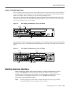
You can identify interface ports by physically checking the slot/port adapter/interface port location
on the back of the router or by using software commands to display information about a specific
interface or all interfaces in the router.
H9710
ETHERNET 10BT
ENABLED
0
2
1
3
LINK
0
1
2
3
FAST SERIAL, ENHANCED
EN
TD
TC
RD
RC
LB
CD
TD
TC
RD
RC
LB
CD
TD
TC
RD
RC
LB
CD
TD
TC
RD
RC
LB
CD
ENABLED
MII
LINK
RJ45
FAST ETHERNET
0
TOKEN RING
0
1
2
3
0
2
4
1
3
5
6
ETHERNET-10BFL
EN
RX
0
1
2
3
4
TX
RX
TX
RX
TX
RX
TX
RX
TX
FAST ETHERNET INPUT/OUTPUT CONTROLLER
ENABLED
PCMCIA
EJECT
SLOT 0
SLOT 1
FE MII
PA-4T+ port adapter
(interface port addresses 1/0, 1/1, 1/2,
1/3 from left to right)
MII
EN
RJ-45
EN
RJ-45
RJ-45
LINK
1O PWR
OK
14620
PA-4T+ port adapter
(interface port addresses 2/0,
2/1, 2/2, 2/3 from left to right)