


Cables and Pinouts
PA-4T+ Synchronous Serial Port Adapter Installation and Configuration1-6
• EIA/TIA-449: DTE mode with a 37-pin D-shell plug (CAB-449MT=); DCE mode with a 37-pin
D-shell receptacle (CAB-449C=).
• V.35: DTE mode or DCE mode with a 34-pin Winchester-type V.35 plug (CAB-V35MT= or
CAB-V35MC=); DTE mode or DCE mode with a 34-pin Winchester-type V.35 receptacle
(CAB-V35FT= orCAB-V35FC=). Alsoavailable isa cablewith a maleDB-60 plugon therouter
end and a male DB-34 shielded plug on the network end (CAB-V35MTS=).
• X.21: DTE mode with a DB-15 plug (CAB-X21MT=); DCE mode with a DB-25 receptacle
(CAB-X21FC=).
• EIA-530: DTE mode with a DB-25 plug (CAB-530MT=).
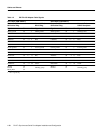
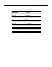
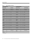
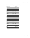
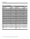
Note For cable pinouts, see the “PA-4T+ Port Adapter Cable Pinouts” section on page 1-9.
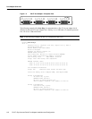
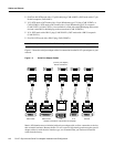
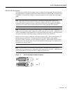
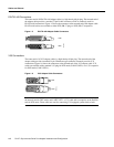
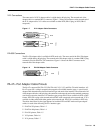
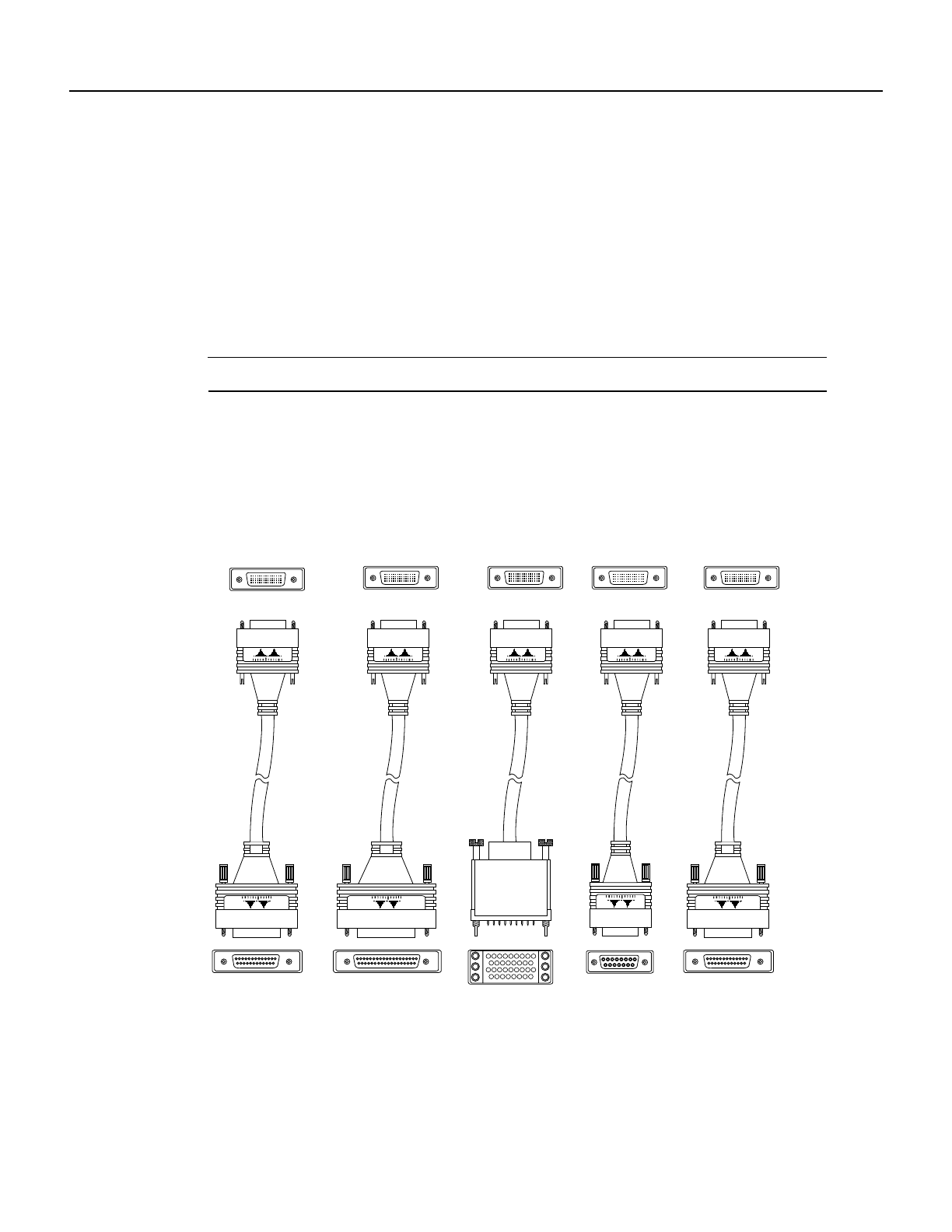
Figure 1-3 shows the serialport adapter cables forconnection from the PA-4T+ port adapters to your
network.
Figure 1-3 Serial Port Adapter Cables
Metric (M3) thumbscrews are included with each port adapter cable to allow connections to devices
that use metric hardware. Because the PA-4T+ uses a special, high-density port that requires special
adapter cables for each electrical interface type, we recommend that you obtain serial interface
cables from the factory.
(PA-4T+ port adapter)
Router connections
EIA/TIA-449 V.35 X.21
Network connections at the modem or CSU/DSU
H10625
EIA/TIA-232 EIA-530