


16
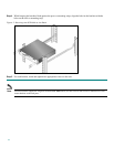
Step 1 Ensure that the DC power line input leads are disconnected from the power source.
Step 2 Using the number 2 Phillips screwdriver, remove the protective plate from the terminal block.
Step 3 Insert one receptacle screw into the hex or loop connector on one power line input, insert the screw with the
connector into the corresponding lead receptacle and tighten the receptacle screw using the number 2 Phillips.
Repeat for the remaining power line input lead.
Note
The color-coding of the DC-input power supply leads depends on the color-coding of the DC power source at your site.
Make certain the lead color coding you choose for the DC-input power supply matches lead color coding used at the DC
power source.
Note
Use 12 AWG (2.5 mm) copper wire only with hex or loop connectors. Ring terminals must be UL approved and suitable for
12 AWG wire.
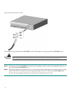
Step 4 Using the number 2 Phillips screwdriver, securely fasten the protective plate to the terminal block.
Step 5 Connect the DC power line input leads to the DC power source through a fast 4A circuit breaker.
Step 6 Turn the on/off switch to the on (⏐) position.
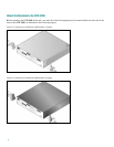
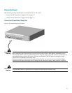
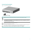
Step 7 Look at the IN and OK LEDs on the power supply unit and the corresponding Power LED on the front panel. If
the DC-input power supply unit is operating properly, these LEDs will be glowing green.
Step 8 Ensure that the power supply is properly aligned and the installation screw is tightened.
This completes the steps for reconnecting the DC-input power supply to the SCE 2000 platform.