


44
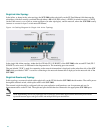
Single Link: Inline Topology
In the inline, or bump-in-the-wire topology, the SCE 2000 resides physically on the FE Fast Ethernet) link between the
subscribers, which are usually connected through either a BRAS (in DSL access), a PDSN (in wireless access), a CMTS
(in the Cable access), or a switch or router aggregator (in other topologies), and the network, where the SCE 2000 usually
connects to a router or layer 3 switch network element.
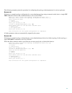
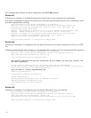
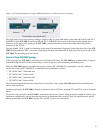
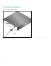
Figure 14: Cabling Diagram for Single Link Inline Topology
In the single link inline topology, either the first FE link (FE-1 SUB/NET) of the SCE 2000 or the second FE link (FE-2
SUB/NET) can be used, as illustrated in the diagram above. The remaining ports are unused.
The port labeled "SUB" is used for connecting to the network element that is deployed on the subscriber side of the SCE
2000 while port labeled "NET" is used for connecting to the network element that is deployed on the network side of the
SCE 2000.
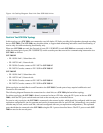
Single Link: Receive-only Topology
In this topology, an external switch resides physically on the FE link that the SCE 2000 should monitor. The traffic passes
through the external switch, which splits traffic to the SCE 2000.
The external switch should be configured with two port replication configurations, one for upstream and one for
downstream traffic on the FE link. The replicated ports should then be connected to the appropriate SCE 2000 ports.
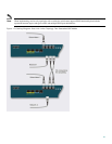
Note
When implementing receive-only topologies with a switch, the switch must support SPAN functionality that includes
separation between ingress and egress traffic and multiple SPAN-ports destinations.