


46
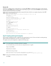
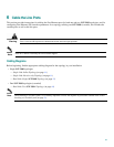
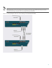
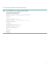
Figure 16: Cabling Diagram: Dual Link One SCE 2000 Inline
Dual Link: Two SCE 2000s Topology
In this topology, two SCE 2000s are connected to two full duplex, FE links, providing full redundancy through cascading
the two SCE 2000s. The SCE 2000s may be either inline, to support both monitoring and traffic control functionality, or
receive-only for traffic monitoring functionality only.
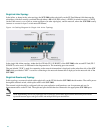
When two SCE 2000s are used, the first pair of ports (FE-1 SUB/NET) in each SCE 2000 are connected to the links,
while the second pair of ports (FE-2 SUB/NET)) are the cascade ports that are used for communicating between the two
SCE 2000s as follows:
SCE 2000 #1
• FE-1 SUB: Link 1, Subscribers side
• FE-1 NET: Link 1, Network side
• FE-2 SUB: Cascade, connect to FE-2 NET in SCE 2000 #2
• FE-2 NET: Cascade, connect to FE-2 SUB in SCE 2000 #2
SCE 2000 #2
• FE-1 SUB: Link 2, Subscribers side
• FE-1 NET: Link 2, Network side
• FE-2 SUB: Cascade, connect to FE-2 NET in SCE 2000 #1
• FE-2 NET: Cascade, connect to FE-2 SUB in SCE 2000 #1
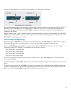
Inline topologies can both Receive and Transmit to the SCE 2000. Cascade ports always require both Receive and
Transmit to be connected.
The following diagram illustrates the connections for a dual link, two SCE 2000-platform inline topology
For inline topologies, the SCE 2000 is directly connected to the two FE links, using the FE-1 ports on the two SCE
2000s, while the FE-2 ports on both units are used as the cascade ports, as described above.
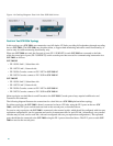
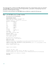
For receive-only topologies, the SCE 2000 is connected to the external switch, which should be configured with four port
replication configurations, one for upstream and one for downstream traffic for each FE link. (Alternatively, two external
switches may be used, one for each link, with each configured with two port replication configurations.) The replicated
ports should then be connected to the SCE 2000s using the FE-1 ports as described above. The FE-2 ports on each SCE
2000 are used as the cascade ports.