


37
The following examples present the procedure for configuring the topology-related parameters for various topologies.
E
XAMPLE #1:
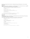
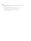
Following is a sample topology configuration for a non-redundant topology using an external switch, that is, a single SCE
2000 connected in receive-only connection mode, to one or two FE links
Would you like to enter the Topology configuration menu? [no]: y
Would you like to enter the Topology configuration menu? [no]: y
Enter Connection mode:
1- inline
2- receive-only
Enter your choice [1]: 2
Is this a cascade deployment? [no]: no
Enter admin status of the SCE after abnormal boot:
1- Operational
2- Not-Operational
Enter your choice [1]: 1
Data collection for the system configuration is completed.
All other parameter values are automatically assigned by the system.
EXAMPLE #2:
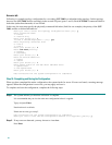
Following is a sample topology configuration for a non-redundant bump-in-the-wire (inline) topology. In this topology, a
single SCE 2000 is connected to one or two FE links.
When the inline connection mode is specified, the user must specify the on-failure link behavior.
Would you like to enter the Topology configuration menu? [no]: y
Enter Connection mode:
1- inline
2- receive-only
Enter your choice [1]: 1
Is this a cascade deployment? [no]: no
Enter On-failure behavior:
1- bypass
2- cutoff
Enter your choice [1]: 1
Enter admin status of the SCE after abnormal boot:
1- Operational
2- Not-Operational
Enter your choice [1]: 1
Data collection for the system configuration is completed.