


38
EXAMPLE #3:
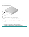
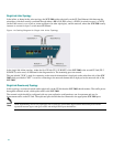
Following is a sample topology configuration for a secondary SCE 2000 in a redundant inline topology. In this topology
there are two SCE 2000s that are cascaded via the cascade FE ports (ports 3 and 4). Each SCE 2000 is connected inline to
both sides (subscribers/network) of one FE link.
In this case, the user must specify the physically-connected-link index (link-0 in our example), the priority of the SCE
2000, and the on-failure link behavior.
Would you like to enter the Topology configuration menu? [no]: y
Enter Connection mode:
1- inline
2- receive-only
Enter your choice [1]: 1
Is this a cascade deployment ? [no]: yes
Enter Physically connected link:
0- link-0
1- link-1
Enter your choice [0]: 0
Enter SCE 2000 priority:
1- primary
2- secondary
Enter your choice [1]: 2
Enter On-failure behavior:
1- bypass
2- cutoff
Enter your choice [1]: 1
Enter admin status of the SCE after abnormal boot:
1- Operational
2- Not-Operational
Enter your choice [1]: 1
Data collection for the system configuration is completed.
Step 10: Completing and Saving the Configuration
When you have completed the entire configuration, the system checks for errors. If errors are found, a warning message
appears. When the configuration is error-free, you may apply and save it.
To complete and save the configuration, complete the following steps:
Step 1 The system informs you that data collection is complete.
It is recommended that you view the entire new configuration before it is applied.
Type y and press Enter.
Note that there is no default.
If there are no errors, go to step 3.
Data collection for the system configuration is completed.
Would you like to view the new configuration before it is applied? [yes/no]: y
Step 2 If any errors are detected, you may choose to view them.
Press Enter.