CY7C63310, CY7C638xx
Document 38-08035 Rev. *K Page 47 of 83
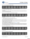
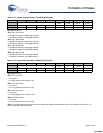
Table 16-12. Capture Interrupt Enable (TCAPINTE) [0x2B] [R/W]
Bit # 7 6 5 4 3 2 1 0
Field Reserved Cap1 Fall
Enable
Cap1 Rise
Enable
Cap0 Fall
Enable
Cap0 Rise
Enable
Read/Write ––––R/W R/W R/W R/W
Default 0 0 0 0 000 0
Bit [7:4]: Reserved
Bit 3: Cap1 Fall Enable
0 = Disable the capture 1 falling edge interrupt
1 = Enable the capture 1 falling edge interrupt
Bit 2: Cap1 Rise Enable
0 = Disable the capture 1 rising edge interrupt
1 = Enable the capture 1 rising edge interrupt
Bit 1: Cap0 Fall Enable
0 = Disable the capture 0 falling edge interrupt
1 = Enable the capture 0 falling edge interrupt
Bit 0: Cap0 Rise Enable
0 = Disable the capture 0 rising edge interrupt
1 = Enable the capture 0 rising edge interrupt
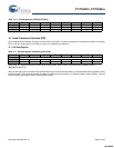
Table 16-13. Capture Interrupt Status (TCAPINTS) [0x2C] [R/W]
Bit # 7 6 5 4 3 2 1 0
Field Reserved TIO1 Fall
Active
TIO1 Rise Active TIO0 Fall
Active
TIO0 Rise Active
Read/Write ––––R/W R/W R/W R/W
Default 0 0 0 0 000 0
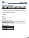
Bit [7:4]: Reserved
Bit 3: TIO1 Fall Active
0 = No event
1 = A falling edge has occurred on TIO1
Bit 2: TIO1 Rise Active
0 = No event
1 = A rising edge has occurred on TIO1
Bit 1: TIO0 Fall Active
0 = No event
1 = A falling edge has occurred on TIO0
Bit 0: TIO0 Rise Active
0 = No event
1 = A rising edge has occurred on TIO0
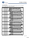
Note The interrupt status bits must be cleared by firmware to enable subsequent interrupts. This is achieved by writing a ‘1’ to
the corresponding Interrupt status bit.
[+] Feedback [+] Feedback


