


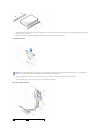


Ensure that the rail tabs are positioned at the back of the hard drive.
5. Remove the first hard drive from the upper bay and install it in the lower bay.
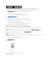
a. Disconnect the power cable and the data cable from the back of the first hard drive.
b. Press in the two green rail tabs and pull the first hard drive out of the upper bay.
c. Gently slide the first hard drive into the lower bay until you hear a click.
d. Reconnect the power cable and the data cable to the back of the hard drive.
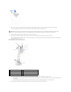
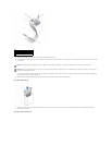
6. Gently slide the new hard drive into the upper bay until you hear a click.
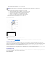
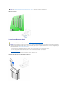
Second Hard Drive Installed
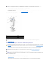
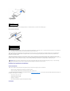
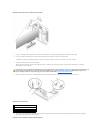
7. Locate the extra connector on the drive cable that is attached to the first hard drive and attach the connector to the second hard drive.
For more information, see "IDE Drive Addressing."
IDE Drive Addressing
All IDE devices require that you configure the cable select setting, which assigns master and slave status to devices according to their position on the
interface cable. You usually configure a drive for cable select by setting a jumper or switch, depending on the drive. Refer to the drive documentation in your
upgrade kit for information on configuring devices for the cable select setting. When you connect two IDE devices to a single IDE interface cable and configure
them for the cable select setting, the device attached to the last connector on the interface cable is the master or boot device (drive 0), and the device
attached to the middle connector on the interface cable is the slave device (drive 1).
With the two IDE interface connectors on the system board, your computer supports up to two IDE devices. IDE hard drives should be connected to the IDE
interface connector labeled "IDE PRI." (Always connect removable media drives to the IDE interface connector labeled "IDE SEC.")
Connecting Drives
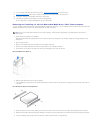
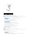
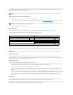
When you install a drive, you connect two cables—a DC power cable and an interface cable—to the back of the drive. Your drive's power input connector (to
which you connect the DC power cable) resembles the following connector.
Power Cable Connector
NOTICE: Do not install a drive into the lower hard-drive bay until you remove the green drive rails from inside the hard-drive cage.
1
rail tabs (2)
2
second hard drive in upper bay
3
first hard drive in lower bay
4
hard drive cage
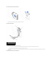
NOTICE: Match the colored strip on the cable with pin1 on the drive.