


Cabling the Cluster Hardware 2-1
Chapter 2
Cabling the Cluster Hardware
T
he Dell PowerEdge Cluster must be installed and
cabled correctly to ensure that the cluster functions prop-
erly. This chapter instructs you on how to cable your
system hardware for a cluster configuration.
Information about configuring your PowerEdge Cluster
is provided in Chapter 3, “Configuring the Cluster
Software.”
For instructions on installing the Microsoft Windows NT
Server Enterprise Edition operating system and the
Microsoft clustering software, refer to the Microsoft
Windows NT Server Enterprise Edition Administrator’s
Guide and Release Notes and the Microsoft Windows NT
Cluster Server Administrator’s Guide. For installation
and configuration information specific to the Dell
PowerEdge 4200 systems or the Dell PowerEdge
Scalable Disk System 100 (SDS 100) storage system,
refer to the Dell documentation for those systems.
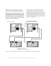
C
luster Cabling
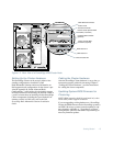
The PowerEdge Cluster consists of two PowerEdge 4200
server systems, one or two PowerEdge SDS 100 storage
systems, a 3Com SuperStack II Switch 3000 TX, and a
pair of power strips or a single power distribution unit,
depending on how the system is configured. These com-
ponents are interconnected as follows:
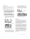
•
A 4-meter (m) small computer system interface (SCSI)
cable is connected from the RAID controller in each
PowerEdge system to the SDS 100 storage system(s).
•
A system management bus (SMB) cable is con-
nected from the SMB connector on one of the two
PowerEdge systems (preferably the system desig-
nated as Node 1 or the primary node) to the SMB
connector on the SDS 100 storage system.
•
Category 5 Ethernet cables are connected from each
of the network interface controllers (NICs) in each
PowerEdge system to the 3Com switch.
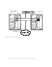
•
Power cables are connected according to the safety
requirements for your region:
— For customers in the Americas: Power cables
for the cluster components are routed through
two Power Techniques power strips. The pri-
mary power supplies of the cluster components
are all cabled to one power strip, and the redun-
dant power supplies on the components are all
cabled to the second power strip. Each power
strip is connected, via Type B plugs and connec-
tors, to a separate alternating current (AC)
circuit, each with a minimum power capacity of
20 amperes (amps).
— For customers in Europe: All power cables are
connected to one or two Marway power distri-
bution units (PDUs), Model MPD-411013 or
two Power Techniques power strips with Type B
plugs, Model P906200.
The following sections describe each of these cabling
procedures.
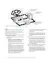
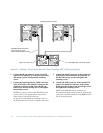
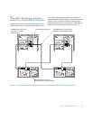
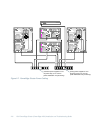
O
ne Shared Storage Subsystem
Cabled to a Cluster
Use the following procedure to connect your cluster
system to a single SDS 100 storage system. Refer to
Figure 2-1 for a diagram of the cabling scheme.
CAUTION: Do not turn on the PowerEdge 4200
systems or the SDS 100 storage system(s) until all
cabling is complete.