


Cabling the Cluster Hardware 2-7
P
ower Cabling
Observe the following warnings when connecting the
power cables to your PowerEdge Cluster system:
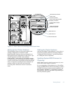
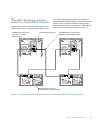
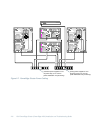
Figure 2-7 illustrates the proper power cabling of the
PowerEdge Cluster components. Each component of the
cluster must have power supplied by two separate AC
circuits—one circuit to each component power supply.
Therefore, the primary power supplies of all the Power-
Edge Cluster components are grouped onto one circuit
and the redundant power supplies are grouped onto
another circuit.
M
ouse, Keyboard, and Monitor
Cabling
If you are installing the PowerEdge Cluster in a Dell
Rack-Mountable Solutions cabinet, refer to the Dell
PowerEdge Rack-Mountable Solutions Installation
Guide for instructions on cabling each cluster node’s
mouse, keyboard, and monitor to the Apex Outlook
switch box in the rack. The switch box enables you to use
a single mouse, keyboard, and monitor for both systems.
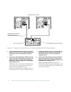
D
isconnecting SCSI Cables
While the Cluster Is Running
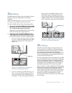
If you must disconnect a SCSI cable between a powered-
down server and a running SDS 100 storage system, you
should first disconnect the cable from the back of the
SDS 100 and then disconnect the cable from the RAID
controller connector on the cluster node. This helps main-
tain the integrity of the SCSI signals while removing the
cable.
WARNING: Although each component of the
PowerEdge Cluster meets leakage current safety
requirements, the total leakage current may
exceed the maximum that is permitted when the
components are used together. To meet safety
requirements in the Americas, you must use a
Type B plug and socket connection for the cluster
power to enable the appropriate level of ground
protection. In Europe, you must use one or two
power distribution units (PDUs) or two Type B
plug and socket connections wired and installed
by a qualified electrician in accordance with the
local wiring regulations.
WARNING: Do not attempt to cable the Power-
Edge Cluster to electrical power without first
planning the distribution of the cluster’s electrical
load across available circuits. For operation in the
Americas, the PowerEdge Cluster requires two
AC circuits with a minimum capacity of 20 amps
each to handle the electrical load of the system. Do
not allow the electrical load of the system to
exceed 16 amps on either circuit. For operation in
Europe, the PowerEdge Cluster requires two cir-
cuits rated in excess of the combined load of the
attached systems. Please refer to the ratings
marked on the back of each cluster component
when determining the total system’s electrical
load.