


2-2 Dell PowerEdge Cluster (PowerEdge 4200) Installation and Troubleshooting Guide
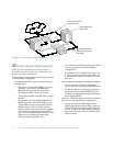
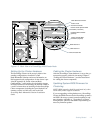
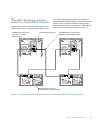
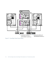
Figure 2-1. Cabling a Clustered System With One PowerEdge SDS 100 Storage System
1. Connect the 68-pin connector on the 4-m SCSI
cable to SCSI connector A on the back of the SDS
100 storage system, and tighten the retaining
screws.
2. Connect the ultra-high density (UHD) connector
of the SCSI cable to the channel 0 connector (the
rightmost connector) on the cluster RAID con-
troller in the first PowerEdge server, and tighten
the retaining screws.
NOTES: On clusters with a single SDS 100 storage
system, either server system can be connected to
either storage system SCSI connector.
Be sure to securely tighten the retaining screws on
the SCSI connectors to ensure a reliable connection.
3. Connect the 68-pin connector on the second 4-m
SCSI cable to SCSI connector B on the back of
the SDS 100 storage system, and tighten the
retaining screws.
4. Connect the UHD connector of the second SCSI
cable to the channel 0 connector on the cluster
RAID controller in the second PowerEdge server,
and tighten the retaining screws.
NOTE: If the SDS 100 storage system is ever
disconnected from the cluster, it must be reconnected
to the same controller channels on the RAID control-
lers to operate properly.
PowerEdge SDS 100 storage system
Ultra/Wide SCSI connections
from channel 0 on each
cluster-enabled RAID controller
68-pin connectors (2)
ultra-high density connector