


Cabling the Cluster Hardware 2-5
S
MB Cabling
The SMB connector enables a host PowerEdge system to
provide system-level management of the storage
system(s).
NOTE: The SDS 100 storage system is connected to only
one of the two PowerEdge systems in the cluster.
To install the SMB cable, use the following procedure:
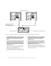
1. Connect one end of the SMB cable (supplied with
the storage system) to the SMB connector labeled
“IN” on the storage system’s back panel.
Both connectors on the SMB cable are identical. The
connectors are keyed for proper insertion.
2. Connect the other end of the SMB cable to the
SMB connector on the first PowerEdge system or
to the SMB connector of the first storage system.
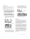
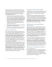
•
If you are connecting only one storage system to
the cluster, connect the SMB cable to the SMB
connector on the first node of the cluster (see
Figure 2-4).
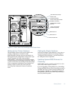
Figure 2-4. SMB Cable Connected to
One SDS 100 Storage System
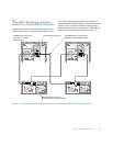
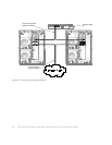
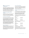
•
If you are connecting two SDS 100 storage sys-
tems to the cluster, link the storage systems in
daisy-chain fashion to the PowerEdge system
(see Figure 2-5). The first storage system in the
chain connects to the SMB connector on the
PowerEdge system’s back panel. The second
storage system connects the SMB cable from its
connector labeled “IN” to the connector labeled
“OUT” on the first storage system’s back panel.
Figure 2-5. SMB Cables Connected to
Two SDS 100 Storage Systems
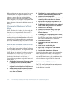
N
IC Cabling
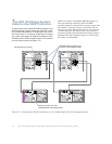
The NICs in the PowerEdge systems provide two net-
work connections on each node—a dedicated network
interconnection between the cluster nodes and a connec-
tion to the local area network (LAN). Having two
network interconnections from each PowerEdge system
can provide redundancy at the communications level in
case one of the cluster NICs fails.
The 3Com SuperStack II switch has eight ports available
on its front panel, running at a switched rate of 100 mega-
bits per second (Mbps). All ports on the SuperStack II
switch are functionally identical, so the NIC cables can
be attached to any of the ports in any order. Category 5
unshielded twisted-pair (UTP) cables are provided.
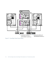
Figure 2-6 shows a sample configuration of NIC cabling
where the private node-to-node interconnect (the NICs in
PCI slot 4 of each node) routes through the network
switch, and the LAN NICs connect directly to the public
LAN. Other configurations are possible, including con-
necting all four NICs to the SuperStack II switch;
however, in this scenario, the switch is a possible single
point of failure.
SMB cable
SMB cables (2)