


1. If you are removing a non-Plug and Play ISA expansion card, enter the ICU and remove the expansion card from your
configuration.
See "Using the ISA Configuration Utility
" for instructions.
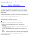
2. Remove the computer cover according to the instructions in See "Removing the Computer Cover
".
CAUTION: See "Protecting Against Electrostatic Discharge".
3. If necessary, disconnect any cables connected to the card.
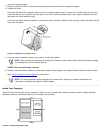
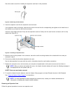
4. Unscrew the mounting bracket of the card you want to remove.
5. Grasp the card by its outside corners, and ease it out of its connector.
6. If you are removing the card permanently, install a metal filler bracket over the empty card-slot opening.
NOTE: Installing filler brackets over empty card-slot openings is necessary to maintain Federal Communications
Commission (FCC) certification of the system. The brackets also keep dust and dirt out of your computer.
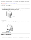
7. Replace the computer cover, and reconnect your computer and peripherals to their power sources and turn them on.
NOTE: After you remove and replace the cover, the chassis intrusion detector will cause the following message to
be displayed at the next system start-up:
ALERT! Cover was previously removed.
8. To reset the chassis intrusion detector, enter the System Setup program and reset Chassis Intrusion to Not Detected.
See "Using the System Setup Program
" for instructions.
NOTE: If a setup password has been assigned by someone else, contact your network administrator for
information on resetting the chassis intrusion detector.
Adding Memory
Dell Precision 610 systems can use unbuffered or registered synchronous dynamic random-access memory (SDRAM) modules that
provide error checking and correction (ECC) capabilities.
System memory can be increased up to 512 megabytes (MB) using unbuffered SDRAM dual in-line memory modules (DIMMs) or
up to 2048 MB using registered SDRAM DIMMs (see Tables 9-1 and 9-2). Unbuffered and registered SDRAM DIMMs cannot be
mixed.
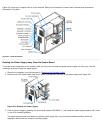
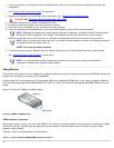
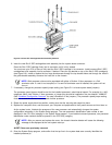
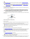
Figure 9-5 shows the DIMMs and DIMM sockets.
Figure 9-5. DIMMs and DIMM Sockets
DIMM Installation Guidelines
When adding system memory, you may install DIMMs in any order. For optimum operation, Dell recommends installing the DIMMs
starting with socket A (closest to the top edge of the system board) and working toward socket D, leaving no open sockets
between installed DIMMs.
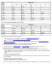
Tables 9-1 and 9-2 list sample memory configurations.
Table 9-1. Sample Unbuffered SDRAM DIMM Configuration Options