


4 DTR O Data terminal ready
5 GND N/A Signal ground
6 DSR I Data set ready
7 RTS O Request to send
8 CTS I Clear to send
9 RI I Ring indicator
Shell N/A N/A Chassis ground
Parallel Port Connector
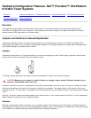
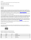
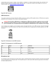
If you reconfigure your hardware, you may need pin number and signal information for the parallel port connector. Figure B-4
illustrates the pin numbers for the parallel port connector, and Table B-4 lists and defines the pin assignments and interface signals
for the parallel port connector.
Figure B-4. Pin Numbers for the Parallel Port Connector
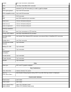
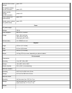
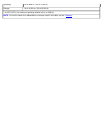
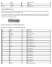
Table B-4. Pin Assignments for the Parallel Port Connector
Pin Signal I/O Definition
1 STB# I/O Strobe
2 PD0 I/O Printer data bit 0
3 PD1 I/O Printer data bit 1
4 PD2 I/O Printer data bit 2
5 PD3 I/O Printer data bit 3
6 PD4 I/O Printer data bit 4
7 PD5 I/O Printer data bit 5
8 PD6 I/O Printer data bit 6
9 PD7 I/O Printer data bit 7
10 ACK# I Acknowledge
11 BUSY I Busy
12 PE I Paper end
13 SLCT I Select
14 AFD# O Automatic feed
15 ERR# I Error