


Chapter 3 Element Function|ScrEdit Software User Manual
3-28 Revision Apr. 30th, 2007, 2007PDD23000002
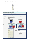
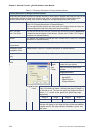
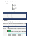
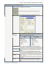
Property Description of Pie Element
Target
Value
Color
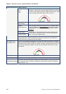
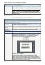
The user can decide if the target value display or not by using
this option. If this option is set, the target value and its color
set by the user will display on the screen. HMI will refer to the
minimum and maximum value and draw the proper reference
line on the bar element just like the figure shown below: (Here
we set the target value is 80 and its color is in yellow.)
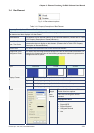
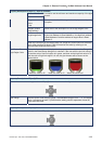
Ranges (Enable range
setting)
Please refer to the description of Low & High Region Color.
Variable target/range
limits
When the target value and low & high limit is a variable value,
the low limit address is Read Address+1, the high limit
address is Read Address+2 and the address of target value is
Read Address+3.
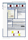
When the user has input the target value, low & high limit, and minimum & maximum
value, after pressing OK button, HMI will examine the value by referring to the selected
data length and data format.
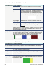
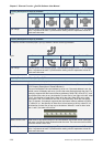
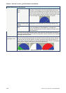
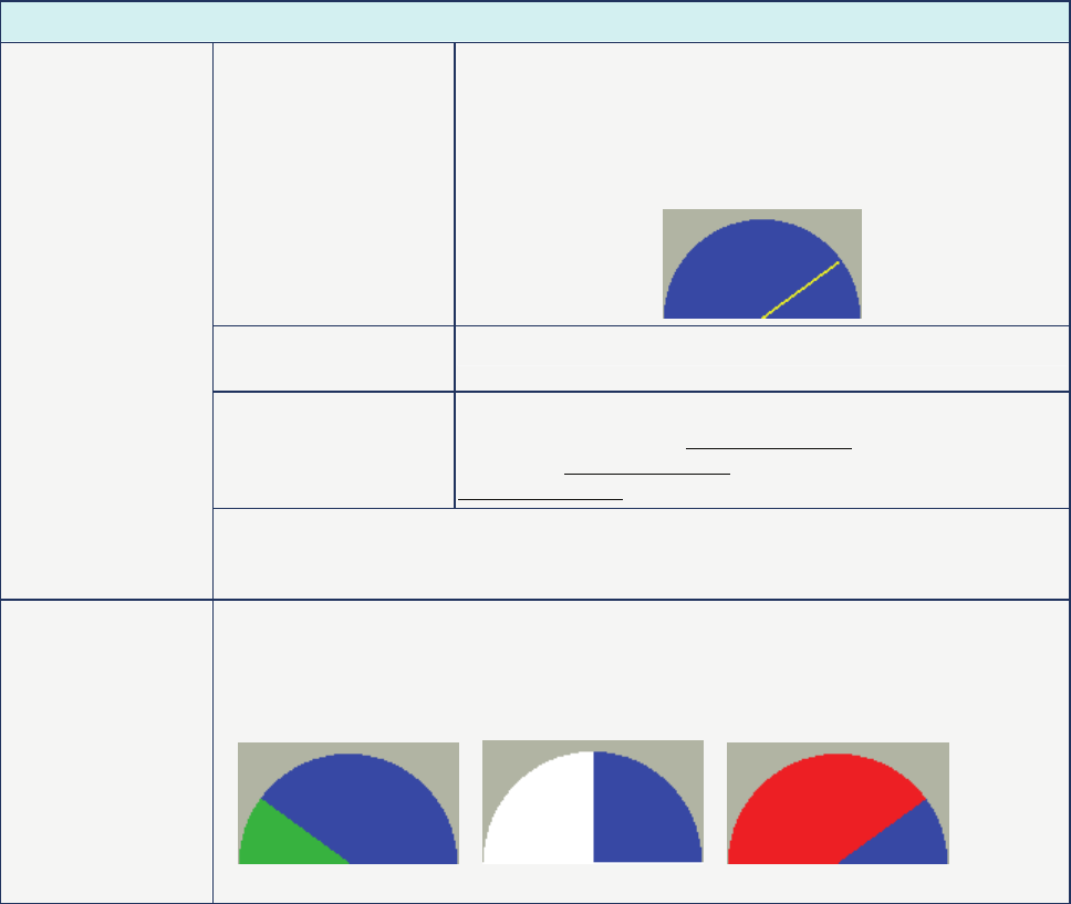
Low Region Color
High Region Color
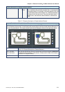
This option is available and displayed in the property table only when the “Ranges”
option in the Detail Setup dialog box is selected. If the user sets the low limit value is
30 and the color of low limit region is in green, and then set the high limit value is 70
and the color of high limit region is in red, the pie element will be shown as the figures
below (The min. & max. input value is 0 and 100 respectively.):
When the value is 20 When the value is 50 When the value is 80