


Chapter 2 Creating and Editing Screens|ScrEdit Software User Manual
2-84 Revision Apr. 30th, 2007, 2007PDD23000002
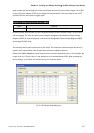
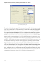
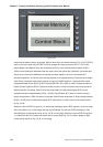
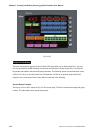
Fig. 2.8.34
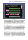
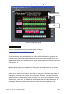
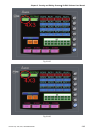
When Internal Memory button is pressed, HMI will enter intro the screen shown as Fig. 2.8.35. RCPG is
used to store the recipe data, RCPNO is used to change the recipe group and RCP0 ~ RCP15 are
recipe registers and HMI will store the recipe data set by the user in these recipe registers. $1000 ~
$1006 are the destination addresses that are used to store the recipe data (Generally, the recipe data
are set to be stored in the addresses of external controller registers, but for the convenience of
simulation operation, we set the recipe storage address in the internal memory). Because this example
uses 32 bits recipe data, each recipe data will occupy two WORD registers. It means that the recipe
storage addresses will be $1000, $1002, $1004 and $1006. $5 in green is used to display the status of
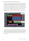
Recipe Control Register (RECR). Recipe Write ($5.2) button is used to execute recipe write operation.
When this button is pressed, HMI will write the recipe data from HMI recipe register RCP into the
designated recipe storage address ($1000 ~ $1006). Recipe Read ($5.1) button is used to execute
recipe read operation. When this button is pressed, HMI will read recipe data of recipe storage address
($1000 ~ $1006) back to HMI recipe register RCP. Main button is used to return to the screen shown
as Fig. 2.8.34.
When the value of RCPG is equal to 0, it means that the display data of RCP register is a 16 bits recipe
data. Since there is no 16 bits recipe data set in this example, the value of RCPG will display 0 only
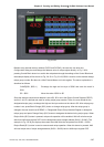
and the display of HMI will be shown as Fig. 2.8.35 on next page. When the value of RCPG is equal to
1, it means that the RCP register will display the B1 recipe data (Fig. 2.8.31) and the display of HMI
screen will be shown as Fig. 2.8.36 on next page.