


Chapter 3 Element Function|ScrEdit Software User Manual
3-40 Revision Apr. 30th, 2007, 2007PDD23000002
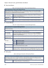
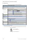
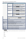
Animated Graphic
Table 3.9.3 Property Description of Animated Graphic Element
Property Description of Animated Graphic Element
When HMI is connected to PLC, the user can create animated graphic elements to read the value of several
read addresses controlled by PLC. The read value of each state can be converted and transmitted to the
animated graphic elements and display on the HMI screen. The individual movement and moving position
can also be controlled and show on the HMI screen.
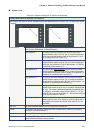
The address can be internal memory or the controller address. (Please refer to Table
3.2.2 Property Description of General Buttons.)
Read Address Use the value of Read Address to switch the state of
animated graphic element.
Read Address+1 Use the value of Read Address+1 to be the horizontal axis
position of the animated graphic element.
Read Address
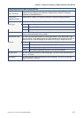
Read Address+2 Use the value of Read Address+2 to be the vertical axis
position of the animated graphic element.
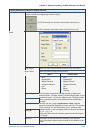
Picture Bank Name
Picture Name
(Please refer to Table 3.2.2 Property Description of General Buttons.)
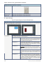
Transparent Effect
Transparent Color
(Please refer to Table 3.2.2 Property Description of General Buttons.)
Clear Picture Use this option to clear previous animated graphic element when moving the element
or changing the state of the element.
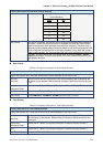
Word It can have 256 states. Data Length
LSB It can have 16 states.
Data Format It provides BCD, Signed Decimal, Unsigned Decimal and Hex four kinds of data
format to define the read memory content.
Add/Remove State It is used to set the state numbers of animated graphic. If the data length of the value
is in Word, 1~256 states can be set. If the data length of the value is in LSB, 16 states
can be set. If the data length of the value is in Bit, only 2 states can be set.
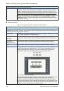
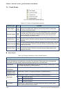
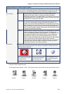
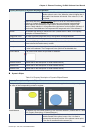
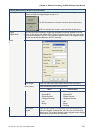
Example of Animated Graphic element:
The designated read address = D100. The internal memory value and each state should be as follows:
State control register Dn+1
X-axis control register Dn+2
Y-axis control register Dn+3