


Chapter 5 Control Block and Status Block|ScrEdit Software User Manual
5-2 Revision Apr. 30th, 2007, 2007PDD23000002
The definition for each function and usage of Control Block and Status Block will be introduced in the
following chapters.
5.1 Control Block
HMI can be controlled via PLC by designating the register from control block settings. The register is a
continuous data block and its length is from 0 to 8 WORD’s. The length is different depends on function. For
example, it needs at least 7 WORD’s for recipe function. When the control block size is set to 0, the control
block function is disabled. If the control block function is enabled, HMI can judge the operation that is
commanded by the external controller by reading the setting in the control block rapidly and continuously.
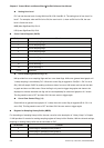
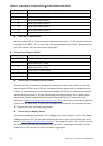
The function and explanation of each WORD are listed below. (In the following table, we assume that the
user uses a Delta PLC, so the available starting addresses in control block are Dn ~ Dn+7 (D0 ~ D7).)
Word Number Register Number Example
0 Register for designating Screen Number (SNIR) Dn (D0)
1 Control Flag Register (CFR) Dn+1 (D1)
2 Curve Control Register (CUCR) Dn+2 (D2)
3 Register for Sampling History Buffer (HBSR) Dn+3 (D3)
4 Register for Clearing History Buffer (HBCR) Dn+4 (D4)
5 Recipe Control Register (RECR) Dn+5 (D5)
6 Register for designating Recipe Number (RBIR) Dn+6 (D6)
7 System Control Flag Register (SCFR) Dn+7 (D7)
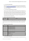
Register for Designating Screen Number (SNIR)
Word Function
0 Designate screen number
This register SNIR (Dn) is used to designate a HMI screen by setting the PLC (D0). An HMI screen can be
switched automatically by changing D0.
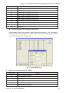
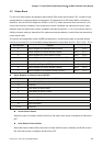
Control Flag Register (CFR)
Bit Number Function
0 Enable / disable communication
1 Enable / disable back light
2 Enable / disable buzzer
3 Clear alarm buffer
4 Clear alarm counter
5~7 Reserved
8 Setting user level bit0
9 Setting user level bit1
10 Setting user level bit2
11~15 Reserved