


Chapter 3 Element Function|ScrEdit Software User Manual
Revision Apr. 30th, 2007, 2007PDD23000002 3-29
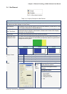
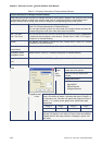
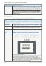
3.7 Indicator
Fig. 3.7.1 Indicator element options
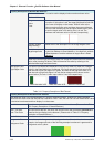
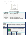
Table 3.7.1 Property Description of Multistate Indicator Element
Property Description of Multistate Indicator Element
Multistate indicator provides a method to indicate the state of some specific address. It will send state
changes message to user no matter it is Bit, LSB or WORD. If this address is an significant indicator or
important message or important alarm, it can be used to inform the user immediately by changing state
display method or different text setting. Or let the user know more information according to the changes of
different states to make the user can also handle the corresponding situation at the first time.
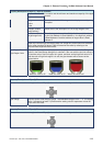
Read Address The address can be internal memory or the controller address. (Please refer to
Table 3.2.2 Property Description of General Buttons.)
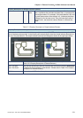
When the read address is set to the contact of the controller, i.e. PLC, the
multistate indicator will change depending on the state (ON or OFF) of PLC
corresponding contact. For example, the user can set that when the value is 1, the
indicator will display the text “Start” and when the value is 0, the indicator will
display the text “Stop”. The user also can add a picture into each state of the
multistate indicator and then the corresponding picture will show when each state is
activated.
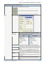
Text / Text Size
Font / Text Color
The user can set the text, text size, font and text color that provided by Windows®
to determine the text display on the element. (Please refer to Table 3.2.2 Property
Description of General Buttons.)
Twinkle The element can twinkle to remind the user. (Please refer to Table 3.2.2 Property
Description of General Buttons.)
Picture Bank Name
Picture Name
(Please refer to Table 3.2.2 Property Description of General Buttons.)
Transparent Effect
Transparent Color
(Please refer to Table 3.2.2 Property Description of General Buttons.)
Foreground Color
Style
(Please refer to Table 3.2.2 Property Description of General Buttons.)
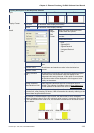
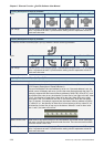
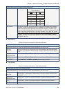
Bit Indicator element can have two states.
Word Indicator element can have 256 states.
Data Length
LSB Indicator element can have 16 states.
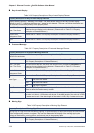
Data Format It provides BCD, Signed Decimal, Unsigned Decimal and Hex four kinds of data
format to display the read memory content.
Add/Remove State It is used to set the state numbers of multistate indicator. If the data length of the
value is in Word, 1~256 states can be set. If the data length of the value is in LSB,
16 states can be set. If the data length of the value is in Bit, only 2 states can be
set.