


Chapter 3 Element Function|ScrEdit Software User Manual
3-30 Revision Apr. 30th, 2007, 2007PDD23000002
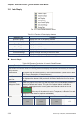
Table 3.7.2 Property Description of Range Indicator Element
Property Description of Range Indicator Element
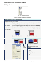
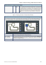
Range indicator provides a method to indicate the state of some specific address. HMI reads the value of the
corresponding address (register) and uses this read value to correspond with the corresponding range
indicator element and its setting value, and then display the corresponding state on HMI screen.
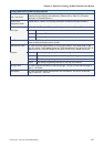
Read Address The address can be internal memory or the controller address. (Please refer to
Table 3.2.2 Property Description of General Buttons.)
The user also can add a picture into each state of the range indicator and then the
corresponding picture will show when each state is activated.
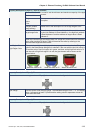
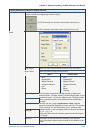
Text / Text Size
Font / Text Color
The user can set the text, text size, font and text color that provided by Windows®
to determine the text display on the element. (Please refer to Table 3.2.2 Property
Description of General Buttons.)
Twinkle The element can twinkle to remind the user. (Please refer to Table 3.2.2 Property
Description of General Buttons.)
Picture Bank Name
Picture Name
(Please refer to Table 3.2.2 Property Description of General Buttons.)
Transparent Effect
Transparent Color
(Please refer to Table 3.2.2 Property Description of General Buttons.)
Foreground Color
Style
(Please refer to Table 3.2.2 Property Description of General Buttons.)
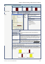
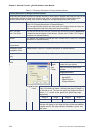
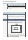
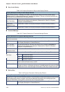
Add/Remove State It is used to set the state numbers of range indicator. 1~256 states can be set.
Data
Length
There are 16bits Word and 32bits
Double Word two options.
There are following data format
provided:
Word/Double Word
Data
Format
1. BCD
2. Signed BCD
3. Signed Decimal
4. Unsigned Decimal
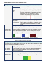
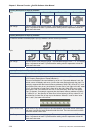
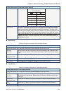
Selecting this option can use default 5 states to set the range. If
there is n numbers of states, it indicates that there is Range n-1
for the user to use. The user can specify the foreground color of
state 0, 1, 2, 3, and 4 as red, green, blue, yellow and purple
respectively.
Range 0 Range 1 Range 2 Range 3
100 50 33 1
Detail
Range Constant
Limits
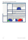
When the value of read address is higher than 100, the range
indicator will display in red. When the value of the read address
is higher than 50, the range indicator will display in green, and
vise versa.