


13
Dialogic
®
SS7G21 and SS7G22 Signaling Servers Hardware Manual Issue 7
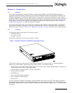
Depending on the variant, an SS7G21 can contain one of the following:
• Up to three Dialogic
®
SPCI2S boards, each providing two T1/E1 interfaces and two V.11 serial ports
• Up to three Dialogic
®
SPCI4 boards, each board providing four T1/E1 interfaces
Each SPCI2S and SPCI4 board supports 4 SS7 links, giving the SS7G21 a maximum capacity of 12 SS7 links.
Depending on the variant, an SS7G22 can contain:
• Up to three Dialogic
®
SS7HDP boards, each board providing four T1/E1 interfaces
• The SS7G22 can optionally be obtained without SS7 signaling boards, typically for use in IP signaling
applications
Each SS7HDP board supports up to 64 SS7 links, and the maximum capacity of an SS7G22 is 128 SS7 links.
For information on the signaling interfaces provided by standard products, refer to Section 2.11,
“Applicability” on page 14.
For more information on the SPCI2S and SPCI4 signaling boards, refer to the SPCI2S, SPCI4 User Manual.
For more information on the SS7HDP signaling board, refer to SS7HDP Installation Guide (card) and SS7HDP
Regulatory Notices.
2.8 Ethernet Ports
The SS7G21 and SS7G22 provide four Gbit/s Ethernet ports. Two of these ports are provided on the Server
Board; the other two are provided by a pre-installed low-profile Ethernet PCI board.
2.9 Cooling
The product contains a fan array consisting of two 80 x 38mm fans and two 40 x 28mm fans to cool the
Server Board and other components. Air flows in through the front bezel over the peripheral bay and the
hard drive bays, passes through the fans and over the baseboard, and exhausts through the rear of the
chassis. The power supplies have their own cooling ventilation. A fan failure is indicated by one of the alarm
LED's located on the front panel. See also the Caution relating to ventilation on page 12.
2.10 Related Information
The documentation set for the SS7G2x includes:
• Dialogic
®
SS7G21 and SS7G22 Signaling Servers Hardware Manual (05-2300)
• Dialogic
®
SS7G2x Signaling Server SIU Mode Migration Guide (05-2303)
• Dialogic
®
SS7G2x Signaling Server SIU Mode User Manual (05-2302)
• Dialogic
®
SS7G2x Signaling Server DSC Mode User Manual (05-2306)
• Dialogic
®
SS7G2x Signaling Server SGW Mode User Manual (05-2304)
In this manual, the term SS7G2x <Operating Mode> User Manual is used to refer to any one of the three
user manuals above.
The following documents provide information about the Dialogic
®
SS7 Signaling Boards that can be installed
in an SS7G21 or SS7G22:
• SPCI2S, SPCI4 User Manual (U04HSP)
• SS7HDP Installation Guide (60-0435)
• SS7HDP Regulatory Notices (60-0027)
The latest software and documentation supporting Dialogic
®
SS7G2x products is available on the web at
http://www.dialogic.com/support/helpweb/signaling.
The product data sheet accessible via
http://www.dialogic.com/support/helpweb/signaling.