


84
Appendix A
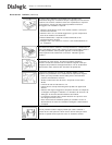
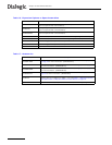
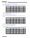
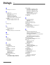
A.1.2.1 Connecting an SPCI2S to an M34 Block Connector
The following table provides information on connecting an SPCI2S (working as a DTE) to a V.35 block
connector (working as a DCE).
Also, it may be necessary to connect:
• M34 pin E (DCERDY-P/DSR) to M34 pin H (DTERDY-P/DTR) and
• M34 pin C (RTS-S) to pin D (CTS-P)
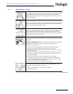
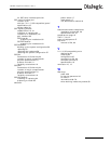
A.1.2.2 Connecting an SPCI2S to a Nortel DMS100
The following information has also been used in conjunction with a Nortel™ DM100™ (25-pin D-type
connector).
Also, it may be necessary to loopback control signals at the Nortel connector if it is not possible to disable
their function. The Nortel switch must be set to DCE mode.
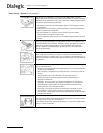
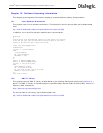
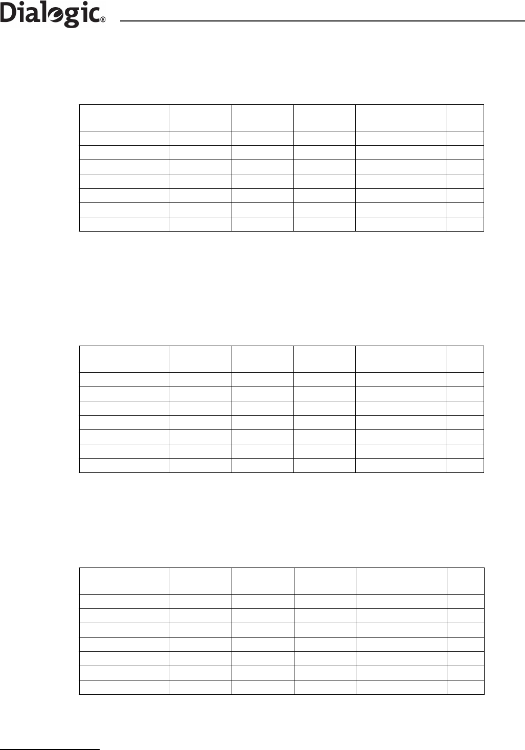
A.1.2.3 Connecting an SPCI2S to an INET Tester
The following information has been used to connect an SPCI2S to an INET™ tester (Turbo7/Spectra) using a
25-pin D-type connector.
V.11 signal name
Port A pin on
SPCI2S
Port B pin on
SPCI2S
DKL26
Y-cable pin
M34 signal name
M34
pin
Received true data 26 9 4 RD-N T
Received inv data 25 8 11 RD-P R
Transmit true data 22 5 2 TD-N S
Transmit inv data 21 4 9 TD-P P
Receive true clock 24 7 6 XMITCLK(DCE)-N AA
Receive inv clock 23 6 13 XMITCLK(DCE)-P Y
Signal Ground 10 10 8 SIGNALGND B
V.11 signal name
Port A pin on
SPCI2S
Port B pin on
SPCI2S
DKL26
Y-cable pin
Nortel signal name
Nortel
pin
Received true data 26 9 4 RxD-B 8
Received inv data 25 8 11 RxD-A 7
Transmit true data 22 5 2 TxD-B 2
Transmit inv data 21 4 9 TxD-A 1
Receive true clock 24 7 6 TSET-B 4
Receive inv clock 23 6 13 TSET-A 3
Signal Ground 10 10 8 ISOGND 21
V.11 signal name
Port A pin on
SPCI2S
Port B pin on
SPCI2S
DKL26
Y-cable pin
INET Signal name
INET
pin
Received true data 26 9 4 Receive Data – B 16
Received inv data 25 8 11 Receive Data - A 3
Transmit true data 22 5 2 Send Data – B 13
Transmit inv data 21 4 9 Send Data – A 2
Receive true clock 24 7 6 Send Timing - B 14
Receive inv clock 23 6 13 Send Timing – A 15
Signal Ground 10 10 8 Ground 7