


65
Dialogic
®
SS7G21 and SS7G22 Signaling Servers Hardware Manual Issue 7
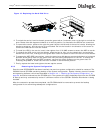
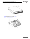
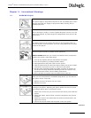
2. To remove the Signaling Board Subsystem, un-latch it from the chassis by placing your thumb on the
rear chassis rail, and your fingers inside the recess at the rear of the Subsystem. A gentle squeeze will
then lift the rear part of the Subsystem and release the Riser Board from its connector. The Signalling
Board Subsystem can then be simply lifted upward out of the chassis.
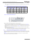
3. Loosen the captive screw, and remove the PCI card keep.
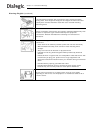
4. If installing an extra SS7 Signaling Board, unscrew and remove the PCI filler bracket from the slot in
which the SS7 Signaling Board is to be inserted. Retain the screw.
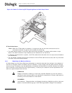
5. If replacing an SS7 Signaling Board, cut the cable tie securing the board to the frame near the PCI card
keep location, as shown in Figure 24. Unplug the CT Bus cable connector from that board. Remove, but
retain, the screw on that PCI end bracket. The SS7 Signaling Board should then be unplugged from the
Riser Board, and be withdrawn from the frame.
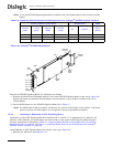
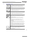
6. Insert or replace the new SS7 Signaling Board, ensuring that the edge connector fully engages in the
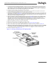
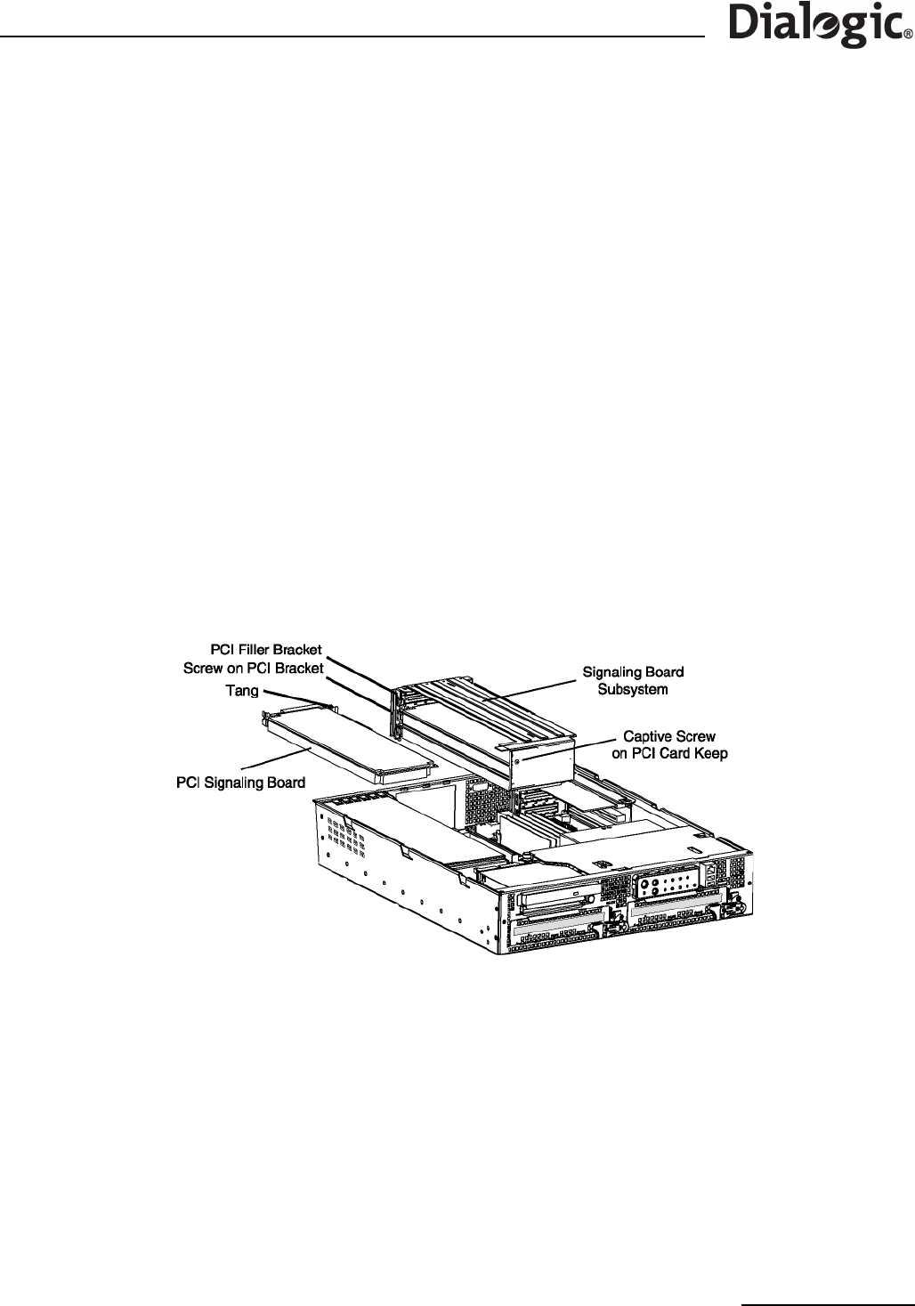
Riser Board socket, and that the PCI end bracket tang (see Figure 23) locates in the loop on the frame.
Take great care to ensure that the EMC gasket (metal) fingers on the inside of the frame are not
damaged, and that the PCI end bracket of the SS7 Signaling Board is centrally aligned to make good
contact with them, and allow clear access for the network interface connectors.
7. Reinstall and tighten the screw on the PCI end bracket.
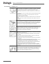
8. Reinstall the PCI card keep, and tighten the captive screw.
9. Connect the CT Bus cable to the SS7 Signaling Board. See CT Bus Cable Notes below.
10.Insert a new cable tie into the SS7 Signaling Board hole, tighten and crop, as shown in Figure 24.
11.Reinsert the Signaling Board Subsystem into the chassis, taking care to make sure that the interlocking
metal tabs on the back of the Signaling Board Subsystem are correctly inserted into the slots in the back
of the chassis, and that the Riser Board edge connector fully engages in the Server Board socket.
12.Install the Top Cover. See Section 10.3.
Figure 23. Installing and Replacing an SS7 Signaling Board