


85
Dialogic
®
SS7G21 and SS7G22 Signaling Servers Hardware Manual Issue 7
A.1.3 Clocking
Physically, the SPCI2S has two sets of clock pins for each serial port. These are designated “Transmit Clock”
and “Receive Clock”. The “Transmit Clock” is always an output, while the “Receive Clock” is always an input.
The following clocking modes are currently supported:
1. SPCI2S/SIU Generates Clocking
In this mode, the “Transmit Clock” signal is driven (at 64kb/s) by the SPCI2S/SIU. This signal is used to
generate the transmit data and clock in the received data.
2. SPCI2S/SIU Receiving Clock
In this mode, the “Transmit Clock” signal is not used. The “Receive Clock” is applied externally to the
SPCI2S and this is used for both generating the transmit data and clocking in the received data.
Most systems use mode b). However, if you are connecting to a switch that needs to be supplied a clock then
mode a) is appropriate.
The use of transmit or receive clock is achieved by the settings of the MTP_LINK parameters in the SIU
config.txt file appropriately (this is discussed further in Section A.1.4 below).
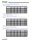
A.1.4 Configuring the SIU (SPCI2S) to Operate on V.11 Ports
In order to configure an MTP link to use the V.11 port correctly, the appropriate settings in the MTP_LINK
command are required. Refer to the appropriate SS7G2x <Operating Mode> User Manual for details.
Section 2.10, “Related Information” on page 13 lists the various user manuals.