83
Dialogic
®
SS7G21 and SS7G22 Signaling Servers Hardware Manual Issue 7
Appendix A
A.1 Connecting to V.11 (V.35-Compatible) SS7 Links
This appendix discusses the issues of connecting SS7G21 product variants which include SPCI2S boards to a
V.35 interface. See the Chapter 12, “Part Number Reference” for the complete list of products variants. Units
designated SS7G21ADxW and SS7G21DDxW have SPCI2S boards pre-installed.
The V.35 interface was originally specified by CCITT as an interface for 48 kbps line transmissions, and was
discontinued by the CCITT (now ITU-T) in 1988, when it was replaced by recommendations V.10 and V.11.
V.35 has been adopted as a standard interface to carry SS7 to an STP in North America. The interface is little
used in Europe and Asia.
V.35 is a mixture of balanced (RS-422 like) and common earth (RS-232 like) signal interfaces. The control
lines including DTR, DSR, DCD, RTS and CTS are single wire common earth interfaces, functionally
compatible with RS-232 level signals. The data and clock signals are balanced,
RS-422 like signals.
There appears to be many different styles of connectors used in SS7 networks for connection to V.35
interfaces; the most common being an M34 “block connector”.
A.1.1 Connectors on the SPCI2S Signaling Board
The SPCI2S provides two V.11 interfaces, designated as port A and port B. Both interfaces are physically
sited on the same connector, that is, a high-density, 26-way D-type (DB) female connector, essentially 26
pins in a standard 15-way back shell. See Section 6.5, “SS7 Serial Interface Ports” on page 36 for more
information.
The V.11 ports on the SPCI2S support clock and data signals only, they do not support any control lines. On
the practical side, this does sometimes mean that it is necessary to loopback one or more control lines to the
remote end of the interconnecting cable, or in some circumstances be disabled at the remote equipment. It
should not be significant in the operation of the SS7 protocol, since SS7 has very good built-in error
detection that quickly detects any break in the signaling path (for whatever reason).
A.1.2 Cabling
Since it may be difficult to obtain a high-density, 26-way, D-type connector, Dialogic is able to supply a “Y”
cable, type DKL26 (product ID SS7DKL26), that connects to the high-density, D-type connector on the rear
of the SPCI2S and terminates in two standard, 15-way, D-connectors (DB15), one connector for each V.11
port.
The details and pinouts for this “Y” cable are provided in the Section 6.5, “SS7 Serial Interface Ports” on
page 36. Suggested pinouts for other possible cabling situations are also described.
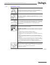
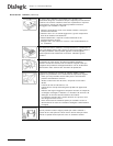
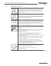
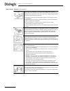
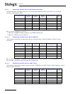
Where this cable is not appropriate, the following sections describe a number of different interconection
examples that may aid the process of selecting the appropriate cabling.
Note: There is no standard for the signal “polarity” or “naming convention”. Therefore, in order to make
the equipment operate correctly, it may be necessary to reverse the connections between the
true and inverted sense of a signal.


