17
Dialogic
®
SS7G21 and SS7G22 Signaling Servers Hardware Manual Issue 7
3.7 Serial Port (COM2)
The serial interface port specification is described as follows:
• Quantity:
One; mounted on the rear of the chassis.
• Connector:
RJ45.
• Electrical:
RS232.
• Signals:
TXD, RXD, DSR, DTR, GND.
3.8 Alarm Outputs
The alarm outputs specification is described as follows:
• Type:
Each alarm (Major, Minor, Critical and *Power) is the output of a SPDT relay contact.
• Designation:
Major, Minor, Critical and Power.
• Contacts:
Single, break before make changeover, voltage free. A common contact with normally open and
normally closed connections is provided.
*Power alarm has just a common and normally open contact outputs.
• Contact rating:
60 VDC maximum.
• Connector type:
15-way, DB15 male connector.
A full list of all alarm types is given in the appropriate SS7G2x <Operating Mode> User Manual.
Section 2.10, “Related Information” on page 13 lists the various user manuals.
3.9 Controls and Indicators
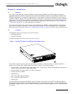
The SS7G21 and SS7G22 include the following switches and indicators. See Figure 3 on page 32 and
Figure 4 on page 33 for the location of the controls and indicators on the front panel and back panels.
Front Panel
• Switch
Toggles the unit power
• Switch
Resets the unit
• CRT Alarm LED (amber)
When lit continuously, indicates the presence of a critical fault. A critical fault is an error or event that is
detected by the unit and indicates failure of an important subsystem that critically degrades operation of
the unit. Some critical faults may indicate an error or event that either has, or may lead to, a fatal failure
of the unit and urgent action should be taken to resolve the cause of the fault. An example is an over
temperature condition due to the failure of the cooling system or the failure of an SS7 Signaling Board.
The critical alarm relay is engaged. The full list of critical alarms is given in the appropriate SS7G2x
<Operating Mode> User Manual. Section 2.10, “Related Information” on page 13 lists the various user
manuals.
• MJR Alarm LED (amber)
When lit continuously, indicates the presence of a major fault. A major fault is an error or event that is
detected by the unit that has a discernible impact on the unit’s operation. In this case, the unit can
continue to operate, but in a “degraded” fashion (that is, with reduced performance or non-fatal loss of
features). Prompt action should be taken to resolve the cause of a Major fault. An example is a Remote
Alarm Indication (RAI) on one of the PCM trunks. The major alarm relay is engaged. The full list of major


