


50
Chapter 9 Product Installation and Hot-Swap Actions
— Configure the product.
10.When installation is complete and the system is operating as intended, consider if you will want to install
a replacement Hard Disk Drive (HDD) in the future. If you do, now is an ideal time to perform a backup
of the System Configuration, which is a necessary step before the HDD can be replaced. For information
on how to back up the System Configuration, read the instructions in Section 9.3.1, “Backing up the
System Configuration” on page 56.
Note: The installer or developer must ensure that the product configuration, and any related
application that is running, provides an implementation that complies with the services offered
by the local Public Switched Telephone Network (PSTN) operator. In case of doubt, network
specifications must be consulted.
9.2 Power Supply Related Actions
There are many different actions that may be required with regard to the Power Supply Modules and their
connections. These can be found in the sub-sections below, or referenced from them, as follows:
• Product Installation, Power Wiring for DC Products
This consists of two essential actions, and one optional action.
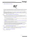
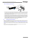
— First connect the Safety Ground Studs as described in Section 9.2.1.
— Carry out initial wiring of a DC Power Supply Module as described in Section 9.2.2.
— If the dual redundant option is required, order and install a second DC Power Supply Module.
Installation of the second module is described below.
• Product Installation, Power Wiring for AC Products
This consists of one essential actions, and one optional action.
— Connection of the AC-input Power Supply Cage is described in Section 9.2.4.
— If the dual redundant option is required, order and install a second AC Power Supply Module.
Installation of the second module is described below.
Note: There is no need to connect the Safety Ground Studs on AC powered products, as the Safety
Ground is provided in the mains cords.
• Second Power Supply Module Installation in DC Products
This operation is basically the same, whether it is carried out at the time of initial installation of the basic
product, or if it is decided to add a second DC Power Supply Module at a later date. The benefits of using
a dual-redundant power supply configuration are described in Section 2.3, “Power Supplies” on page 12.
Removal of the filler module is basically the same as removing a DC Power Supply Module as described in
Section 9.2.5, which also covers the insertion of the DC Power Supply Module, including the use of the
'latches'. Take this opportunity to check that the Safety Ground Stud connection is in good order, as
described in Section 9.2.1. Wiring of the second module follows the description in Section 9.2.2.
• Second Power Supply Module Installation in AC Products
This operation is basically the same, whether it is carried out at the time of initial installation of the basic
product, or if it is decided to add a second AC Power Supply Module at a later date. The benefits of using
a dual-redundant power supply configuration are described in Section 2.3, “Power Supplies” on page 12.
Removal of the filler module is basically the same as removing an AC Power Supply Module as described
in Section 9.2.6, which also covers the insertion of the AC Power Supply Module, including the use of the
'latches'. Connection for the second module simply requires both mains cords to be used on the AC-input
Power Supply Cage, as described in Section 9.2.4.
• Replacement of Power Supply Module in DC Products
The general actions required, such as (un)latching, removal and insertion of modules, are described in
Section 9.2.5.
Transferring of the connections from the 'removed' module, to the 'replacement' module, are described
in Section 9.2.3.
If replacing a failed module, it is possible that the relevant fuse may need replacement. It should be
possible to determine if this is necessary from the LED indication on the new module.