


53
Dialogic
®
SS7G21 and SS7G22 Signaling Servers Hardware Manual Issue 7
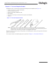
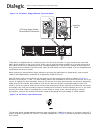
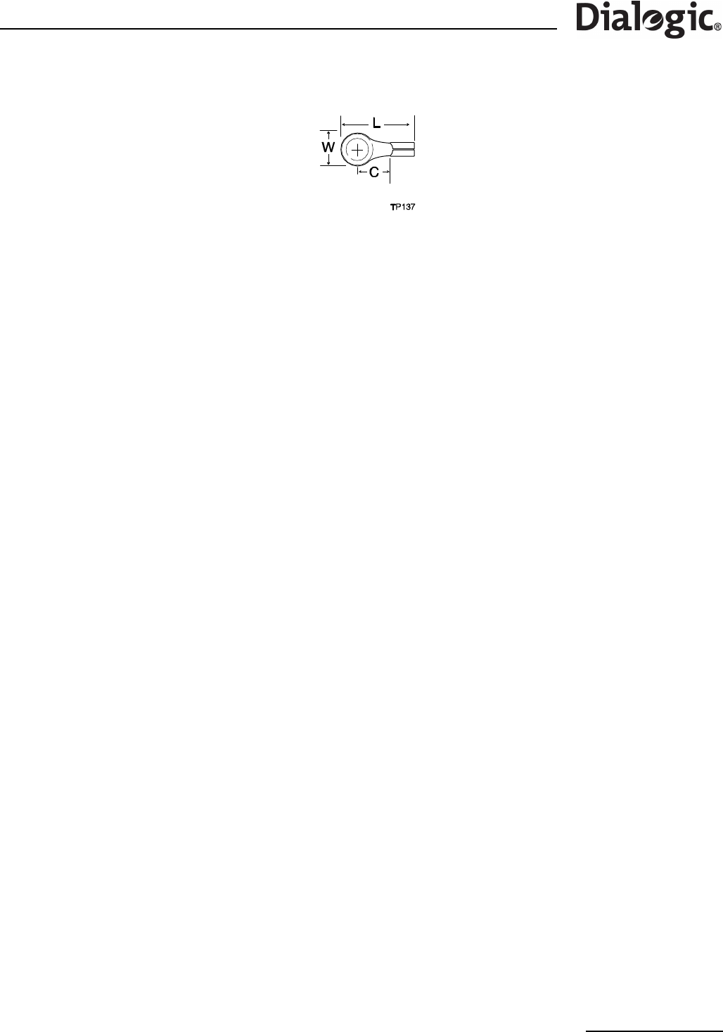
Figure 15. DC Power Terminal Lug
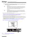
When selecting an appropriately sized power wire, consider the power rating of the product, and the length
of the cable run. When installing the product in locations other than telecommunications centres, ensure that
the cables connecting the DC power input, and the safety ground conductor, are less than 3 metres in
length.
When selecting a suitable DC power source for connection to, ensure that it complies with the WARNING – IF
DC POWER SUPPLIES ARE INSTALLED warning in Chapter 7, “Warnings and Cautions”. This covers the
following aspects; isolation, installation in a restricted-access location, main DC power disconnect, grounding
the rack installation, and overcurrent protection.
9.2.3 DC Power Supply Module, Transferring Connections
When replacing a DC Power Supply Module, the terminal block, with wires attached, can be removed from
the faulty Power Supply Module and assembled to the replacement Power Supply Module as follows:
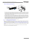
1. Remove the two screws that secure the terminal block to the Power Supply Module and pull the terminal
block away from the module. See Figure 13 on page 52.
Note: Removing the two screws also frees the terminal block cover, but it can be retained by attaching
it to the removed terminal block.
2. Remove the faulty Power Supply Module from the chassis.
3. Install the replacement Power Supply Module. See Section 9.2.5, “Replacing a DC Power Supply Module”
on page 53.
4. On the newly installed Power Supply Module, lift the insulating cover on the terminal block to access the
two screws that secure the terminal block to the chassis.
5. Remove the two screws and carefully pull the terminal block away from the Power Supply Module.
6. Align the old terminal block (with wires attached) with the terminal block receptacle on the new Power
Supply Module and carefully push the terminal block into the Power Supply Module.
7. Secure the terminal block in position using the two securing screws. See Figure 13 on page 52.
8. Close and latch the insulating cover so that it covers the terminals.
9.2.4 AC-input Power Supply Cage, Connection
Two AC power input connectors, type IEC320, are provided at the rear of the Power Supply Cage of AC
powered product. Connection to an AC power outlet is covered in Part I, Section 6.3, “AC Power Input” on
page 35 (it is not essential for it to be performed by a qualified service technician).
9.2.5 Replacing a DC Power Supply Module
Observe the following cautions: