


DES-3550 Fast Ethernet Layer 2 Switch
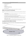
Two 1000BASE-T Mini-GBIC combo ports for connecting to another switch, server, or network backbone. •
• RS-232 DCE Diagnostic port (console port) for setting up and managing the Switch via a connection to a
console terminal or PC using a terminal emulation program.
NOTE: For customers interested in D-View, D-Link Corporation's
proprietary SNMP management software, go to the D-Link Website
(www.dlink.com.cn) and download the software and manual.
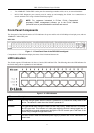
Front-Panel Components
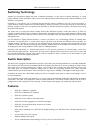
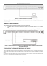
The front panel of the Switch consists of LED indicators for power and for each 10/100 Mbps twisted-pair ports, and two
1000BASE-T Mini-GBIC ports.
DES-3550
Figure 1- 1. Front Panel View of the DES-3550 as shipped
Comprehensive LED indicators display the status of the Switch and the network.
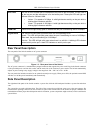
LED Indicators
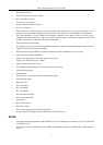
The Switch supports LED indicators for Power, Console, RPS and Port LEDs. The following shows the LED indicators for
the Switch along with an explanation of each indicator.
Figure 1- 2. LED Indicators
LED Description
Power
This LED will light green after the Switch is powered on to indicate the ready state of the
device. The indicator is dark when the Switch is powered off.
Console
This LED should blink during the Power-On Self Test (POST). When the POST is finished,
the LED goes dark. This indicator is lit sold green when the Switch is being logged into via
out-of-band/local console management through the RS-232 console port in the back of the
Switch using a straight-through serial cable.
RPS
This LED will be lit when the redundant power supply is present and in use. Otherwise it will
remain dark.
4