


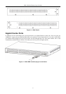

DES-3550 Fast Ethernet Layer 2 Switch
Management Options
This system may be managed out-of-band through the console port on the front panel or in-band using Telnet. The user
may also choose the web-based management, accessible through a web browser.
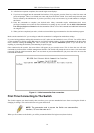
Web-based Management Interface
After you have successfully installed the Switch, you can configure the Switch, monitor the LED panel, and display
statistics graphically using a web browser, such as Netscape Navigator (version 6.2 and higher) or Microsoft® Internet
Explorer (version 5.0).
SNMP-Based Management
You can manage the Switch with an SNMP-compatible console program. The Switch supports SNMP version 1.0, version
2.0 and version 3.0. The SNMP agent decodes the incoming SNMP messages and responds to requests with MIB objects
stored in the database. The SNMP agent updates the MIB objects to generate statistics and counters.
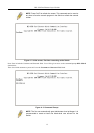
Command Line Console Interface Through The Serial Port
You can also connect a computer or terminal to the serial console port to access the Switch. The command-line-driven
interface provides complete access to all Switch management features.
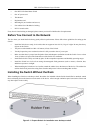
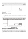
Connecting the Console Port (RS-232 DCE)
The Switch provides an RS-232 serial port that enables a connection to a computer or terminal for monitoring and
configuring the Switch. This port is a female DB-9 connector, implemented as a data terminal equipment (DTE)
connection.
To use the console port, you need the following equipment:
A terminal or a computer with both a serial port and the ability to emulate a terminal. •
• A null modem or crossover RS-232 cable with a female DB-9 connector for the console port on the Switch.
To connect a terminal to the console port:
1. Connect the female connector of the RS-232 cable directly to the console port on the Switch, and tighten the
captive retaining screws.
2. Connect the other end of the cable to a terminal or to the serial connector of a computer running terminal
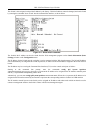
emulation software. Set the terminal emulation software as follows:
3. Select the appropriate serial port (COM port 1 or COM port 2).
4. Set the data rate to 9600 baud.
5. Set the data format to 8 data bits, 1 stop bit, and no parity.
6. Set flow control to none.
7. Under Properties, select VT100 for Emulation mode.
8. Select Terminal keys for Function, Arrow, and Ctrl keys. Ensure that you select Terminal keys (not Windows
keys).
NOTE: When you use HyperTerminal with the Microsoft® Windows® 2000
operating system, ensure that you have Windows 2000 Service Pack 2 or
later installed. Windows 2000 Service Pack 2 allows you to use arrow keys
in HyperTerminal's VT100 emulation. See www.microsoft.com for
information on Windows 2000 service packs.
9. After you have correctly set up the terminal, plug the power cable into the power receptacle on the back of the
Switch. The boot sequence appears in the terminal.
13