


DES-3550 Fast Ethernet Layer 2 Switch
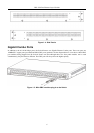
Port LEDs
One row of LEDs for each port is located above the ports on the front panel. The first LED is
for the top port and the second one is for the bottom ports. These port LEDs will light two
different colors for 10M and 100M.
•
•
Amber - For speeds of 10 Mbps. A solid light denotes activity on the port while a
blinking light indicates a valid link.
Green - For speeds of 100 Mbps. A solid light denotes activity on the port while a
blinking light indicates a valid link.
100M/10M
These LEDs will light steady green to indicate that the port is transferring data at 100Mbps.
Gigabit Ports
The Switch's two Mini GBIC ports have their own corresponding LEDs:
Speed - This LED will light solid green when the port is transferring at a rate of 1000Mbps.
When dark, the port is transferring at 10/100Mbps.·
Link/Act - This LED will light solid green when there is a valid link. A blinking LED indicates
current activity on the port. A dark LED indicates no activity on the port.
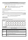
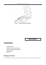
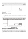
Rear Panel Description
The rear panel of the Switch contains an AC power connector.
Figure 1- 3. Rear panel view of the Switch
The AC power connector is a standard three-pronged connector that supports the power cord. Plug-in the female connector
of the provided power cord into this socket, and the male side of the cord into a power outlet. The Switch automatically
adjusts its power setting to any supply voltage in the range from 100 ~ 240 VAC at 50 ~ 60 Hz.
The rear panel also includes an outlet for an optional external power supply. When power fails, the optional external RPS
will take over all the power immediately and automatically.
Side Panel Description
The right-hand side panel of the Switch contains a system fan, while the left hand panel includes a system fan and a heat
vent.
The system fans are used to dissipate heat. The sides of the system also provide heat vents to serve the same purpose. Do
not block these openings, and leave at least 6 inches of space at the rear and sides of the Switch for proper ventilation. Be
reminded that without proper heat dissipation and air circulation, system components might overheat, which could lead to
system failure.
5