Switching Between Images
(continued)
40
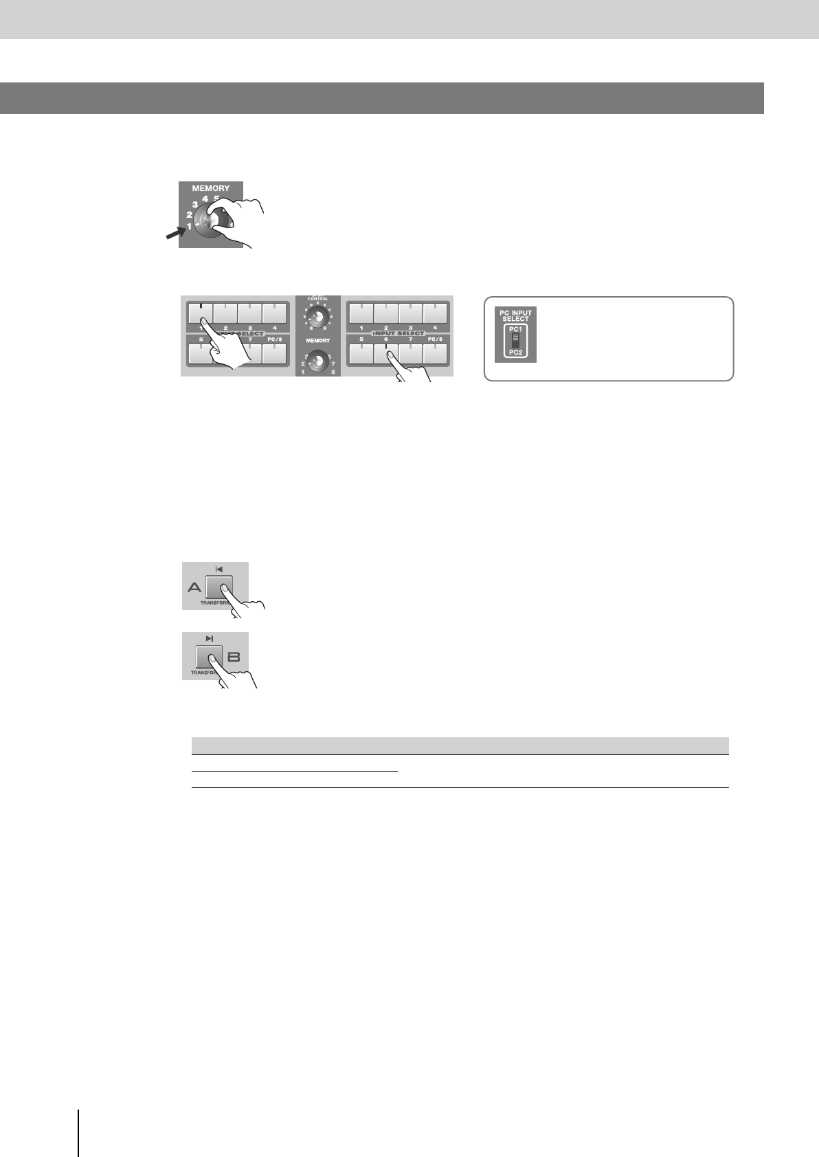
Here’s how you can use the [TRANSFORMER] buttons to switch images without using the video fader.
1
Set the [MEMORY] knob to memory number 1.
* The factory preset settings are assigned to memory number 1. For details on
the [MEMORY] knob, refer to “Storing the Operating Panel Settings” (p. 28).
2
Use the INPUT SELECT buttons to select the images that you want to input to bus A and bus B.
* When you use the [PC INPUT SELECT] switch to switch the PC input, it will take some time for the input to stabilize.
We recommend that you use a monitor to verify the image.
* If you want to adjust the display position or other aspects of the PC input screen, refer to “Adjusting the PC Input
Image” (p. 54).
3
Operate the video fader to output either bus A or bus B.
Set the video fader all the way to either bus A or bus B.
4
Press a [TRANSFORMER] button to switch between the bus A or bus B images.
If the video fader is in the bus B position:
The bus A image will be output only while you hold down the bus A
[TRANSFORMER] button.
If the video fader is in the bus A position:
The bus B image will be output only while you hold down the bus B
[TRANSFORMER] button.
* With the factory preset settings, the [TRANSFORMER] buttons are assigned to operate as follows.
* You can change the operation (the image switching pattern) produced by pressing the [TRANSFORMER] button.
You can also assign a TRANSITION button or EFFECTS button to the [TRANSFORMER] button, and use it to
control a transition or effect.
For details, refer to refer to “Changing the assignment of the [TRANSFORMER] buttons” on the following page.
Menu item Setting Details
Transformer-A
02: Trans
The image of the bus whose [TRANSFORMER] button you hold down will
be output.
Transformer-B
02: Trans
Using the [TRANSFORMER] Buttons to Switch Images
Bus A Bus B
If you’ve selected the [PC/8] button
Use the [PC INPUT SELECT] switch
to change between the PC1 and PC2
connector inputs.
V-8_e.book 40 ページ 2008年5月15日 木曜日 午後1時11分


