


HARSFEN0602
The method described here can work in reliably many practical situations, although it does not fit every
application. If the parameters of the method are not tuned properly, or the method is not good for the
application, the motor starting process will fail.
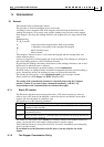
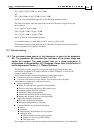
After setting MO=1, the algorithm will try to oscillate the motor and find the commutation angle. If the
results are not reliable, since the oscillation amplitude is too small or since the load behavior is not inertial,
then MO will reset automatically to zero and the motor won’t start.
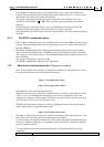
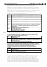
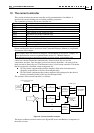
9.4.5 Parameters related to starting the motor with no digital Hall sensors
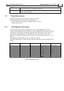
The following parameters are relevant:
Parameter Comment
CA[18],CA[19] The encoder resolution and the number of motor pole pairs.
CA[18] must be greater than CA[19]*256.
CA[20] Must be set to 0 to indicate that Hall sensors are not present
CA[21] Must be set to 1 to indicate that an encoder is present.
CA[15] Set the frequency of the oscillation, as explained above.
CA[24] Set the minimum acceptable oscillation amplitude – set to 4
CA[26] Set the excitation amplitude, as a percentage of the continuous current.
MO MO=1 sets the motor on.
If the motor starting fails, MO resets to 0
WS[15] Reads the actual oscillation amplitude.
WS[16] Flag if a non-inertial behavior has been observed.
9.5 Continuous Vs. Six-Steps commutation
The basic commutation equation for a sinusoidal motor (repeated here for convenience) is
)sin(IKT
rFT
θ−θ⋅⋅=
(1)
Above,
rF
,θθ are the field electrical angle and the rotor electrical angle, respectively.
For optimizing the torque, we have to keep
90
rF
≈θ−θ .
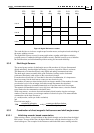
Let us define the commutation error
()
rF
90 θ−θ−=ε , Ideally .0=ε
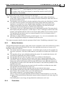
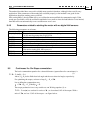
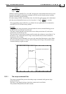
The torque production is not very sensitive to
ε . Writing equation (1) as
)cos(IKT
T
ε⋅⋅= we see that for a miss of 5 , we lose about 0.4% of the torque. With a
miss of 30 , we lose 13.4% of the torque – see figure below.