


HARSFEN0602
The commutation accuracy will be limited by backlash and gear compliance
The motor speed can be measured with better resolution and less delay because the
motor rotates much faster than the load. In addition, the speed sensor is not subject
to dead zones caused by backlash.
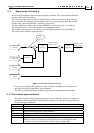
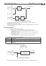
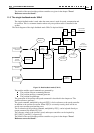
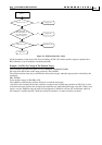
The block diagram of the dual feedback mode UM=4 is depicted below:
Software
position
command
Enable if
RM==1
Auxiliary position
command
Stop
manager
Stop and limit
switches
Smoother
d/dt
Position
Controller
FF[2]
Auxiliary
feedback
encoder
main feedback
encoder
Speed
Estimator
--
DV[3]
DV[2]
Speed
Error
d/dt
Acceleration
feed forward
FF[1]
Position
correction
Figure 22: Dual feedback mode (UM=4)
The position and the speed commands are generated by:
The position software command generator
The position auxiliary command generator
The position Stop Manager
The generation of the position and speed commands is similar to the position and speed
commands generation in UM=4, and will be described later the chapter on "The position
reference generator".
The speed command, multiplied by the gain FF[2], is fed as reference to the speed controller
in addition to the position correction. When FF[2] is set exactly to the gear ratio between the
position sensor and the speed sensor, there will be no steady state constant-speed tracking
error.
The acceleration of the position command, multiplied by FF[1], can be injected directly as
torque command. By default, FF[1]=0.
The reference values to the position, speed, and torque controllers can be inquired by
DV[3],DV[2], and DV[1] respectively.