


HARSFEN0602
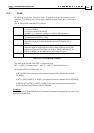
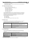
The commands relevant to the stop manager are:
Command Description
SD The maximum rate that the motor can accelerate/decelerate.
IL[N] Input logic – define the functions associated to digital inputs.
VH[N],VL[N] The maximum allowed controller command
XM,YM Modulo count for the main and the auxiliary sensors
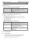
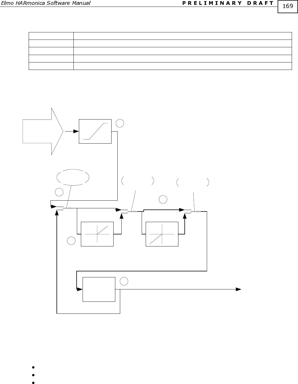
12.3.2 Stop Manager Internals
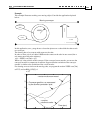
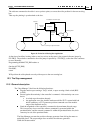
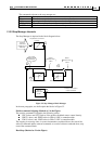
The Stop Manager is depicted in the block diagram below:
Position
command
(Software and
External)
Clip Position command
to range
Select zero
if hard-stop
Prevent backwards motion
Select
direction limit
if RLS
Select
direction limit
if RLS
Prevent Forward Motion
Rate &
Acceleration
limiter
Position command to
motion controller
1
2
3
4
5
Figure 32: Stop Manager Block Manager
In the next paragraphs, we shall explain the blocks in Figure 32.
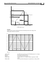
Position command clipping (Marked as 1 in the Figure)
The position command is clipped to the following values:
VH[3] above and VL[3] below, if the position feedback sensor counts linearly.
XM/2-1 above, and -XM/2 below in UM=4, if PX is counted modulo.
YM/2-1 above, and -YM/2 below in UM=5, if PY is counted modulo.
The clipping is necessary since, in some circumstances explained above, the sum of the
software command and the external command, or even the software command alone, may
exceed the command limits.
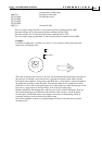
Hard Stop (Marked as 2 in the Figure)