


HARSFEN0602
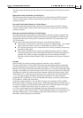
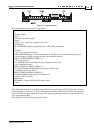
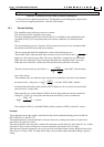
Figure 35 – Switches location
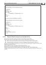
The following user program does the algorithm:
Note that the function above uses MI to prevent RLS from activating the AUTO_RLS routine. Another
possible approach would be to use IL[] to change the functionality of the switch to GPI
7
, and then home
on the GPI. With the latter approach, however, the routine programmer need to know which connector
pin is programmed as RLS.
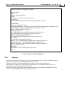
The algorithm used the following helper functions:
7
General Purpose Input
function [int status] = homing1(int TimeOut)
/*
Homing routine.
Input:
TimeOut: Timeout for failure
Output:
status=1 if o.k., otherwise a negative error code
Assumptions:
RLS,FLS,HOME already programmed by IL[1],IL[2],IL[3] commands
*/
int OldMi;
/* Go reverse until limit switch */
OldMi=MI;MI=MI|0x16; /* Prevent operational AUTO_RLS routine while in homing process*/
/* Arm homing for
RLS, stop after homing, don't initialize counter*/
HM[3]=7;HM[4]=0;HM[5]=2;HM[1]=1;
/* Go to the reverse */
JV=-10000;BG;WaitArrive(2000);if(status<=0)goto LastLine; end
/* Go until home switch*/
HM[3]=1;HM[4]=2;HM[5]=2;HM[1]=1;
JV=-JV;BG;WaitHome(2000);if(status<=0)goto LastLine; end
/* Finallyset position by index */
HM[3]=3;HM[4]=0;HM[5]=0;HM[1]=1;
WaitHome(2000);if(status<=0)goto LastLine; end
status=1;/*Success return */
##LastLine
MI=OldMI; ** Restore AUTO_RLS routine status
return